

3.2 - Simple Circuits
Circuit Components
A circuit is made of electrical loops that can include a variety of elements:
- Wires are conductors that connect the components.
- Batteries provide a potential difference (emf).
- Resistors oppose current flow.
- Lightbulbs turn electrical energy into light and heat.
- Capacitors store electric charge.
- Switches open or close paths in the circuit.
- Ammeters measure current.
- Voltmeters measure potential difference.
Electrical Loops
An electrical loop is a closed path that charges can flow through.
Types of Circuits
Closed circuit: there’s a complete path for charges to flow, so current can exist.
Open circuit: the path is broken, often by an open switch. No current flows because the charges can’t complete the loop.
Short circuit: there’s a path where charges can flow with no change in potential difference. This usually means the current skips past other circuit elements, and it often produces dangerously high currents.
Example (shorting a bulb): two identical bulbs, A and B, are in series with a 6.0 V battery, and each bulb has a resistance of 3.0 Ω. Then a wire is connected from one side of bulb B to the other.
- Before the wire: Ω, so A, and each bulb dissipates W.
- After the wire: the wire joins the two ends of bulb B, so they’re at the same potential. With zero potential difference across bulb B, there’s no current in it (), and it goes out. Bulb B has been short circuited: the charge takes the wire instead.
- Bulb A is now the only resistance in the loop: A, and W. Bulb A now dissipates four times as much power, so it gets much brighter (brightness is covered in 3.4).
Multiple Loops
A single circuit element can belong to more than one electrical loop. This happens all the time in complex circuits where current has several possible paths.
Figuring out which loops contain which elements is key to analyzing a circuit.
Circuit Schematics
Circuit schematics are standardized diagrams for representing and analyzing circuits.
A circuit’s properties depend on the physical arrangement of its elements, so how the components are connected really matters.
Example: take one battery and two identical bulbs. Wired in series, the bulbs share the battery’s potential difference, so each one gets half of it. Wired in parallel, each bulb is connected straight across the battery and gets the full potential difference, so both glow brighter than in the series version (3.4 and 3.5 work out the numbers). Same parts, different arrangement, different circuit.
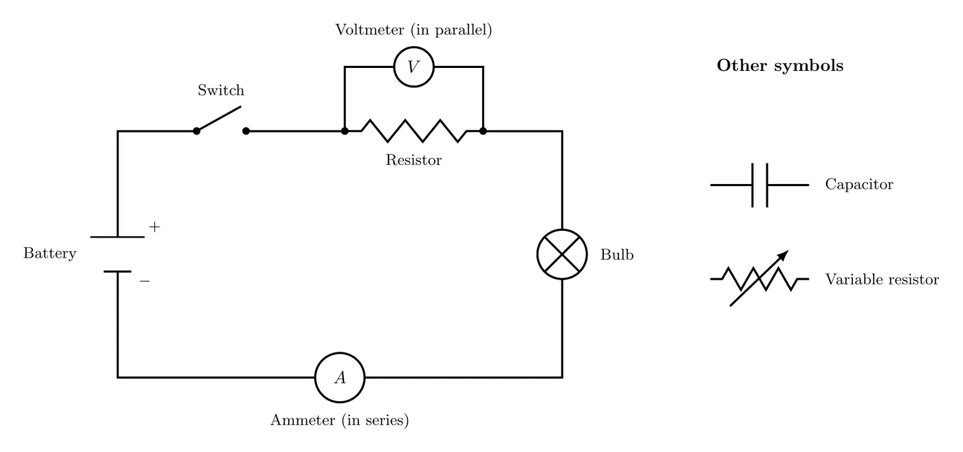
Standard Circuit Symbols
- Battery: two parallel lines, where the longer line is the positive terminal and the shorter line is the negative terminal.
- Resistor: a zigzag line.
- Bulb or light: a circle with an X inside, or a circle with a filament symbol.
- Switch: a break in the line with a diagonal connector.
- Capacitor: two parallel lines that stand for the plates.
- Don’t mix it up with the battery: a capacitor’s two lines are the same length, while a battery’s lines are different lengths (the long one is +).
- Ammeter: a circle with an “A” inside, which measures current and goes in series.
- Voltmeter: a circle with a “V” inside, which measures voltage and goes in parallel.
- Variable elements: shown with a diagonal arrow through the standard symbol, like a variable resistor or variable capacitor.
Convention
Unless a problem says otherwise, all circuit diagrams use conventional current, which is the direction positive charges would flow.
Practice Problems
1. Decide whether each of these is a closed circuit, an open circuit, or a short circuit:
- (a) A battery connected to a resistor with a closed switch.
- (b) A battery connected to a resistor with an open switch.
- (c) A battery connected to a wire with negligible resistance.
2. In a circuit with three resistors set up so current can take two different paths, one resistor is shared by both paths. How many distinct electrical loops are there?
3. Explain why an ammeter has to go in series with a circuit element while a voltmeter has to go in parallel.
4. A student builds a circuit with a battery, two resistors, and a switch. Draw a schematic where (a) both resistors are always in the circuit, and (b) the switch controls whether current flows.
Solutions
1.
- Closed circuit. There’s a complete path for charges to flow from the battery, through the resistor, and back.
- Open circuit. The open switch breaks the path and stops charge flow, even though the battery is still providing a potential difference.
- Short circuit. Charges flow straight through the wire with basically no resistance and no change in potential difference. The battery terminals end up effectively connected directly, which can damage the battery or create hazardous conditions.
2. There are three distinct electrical loops (picture the battery in series with the shared resistor, which then feeds the two parallel resistors):
- Loop 1: through the battery, the shared resistor, and the first parallel resistor.
- Loop 2: through the battery, the shared resistor, and the second parallel resistor.
- Loop 3: the small loop made of just the two parallel resistors (out through one and back through the other).
The shared resistor is part of two of the three loops (Loops 1 and 2), and each parallel resistor is also part of two loops. That’s how one element can belong to more than one electrical loop.
3.
Ammeter (in series): the current is the same everywhere in a series connection. To measure the current through an element, the ammeter has to sit right in the current path so all the current passes through it. An ideal ammeter has zero resistance so it doesn’t change the circuit.
Voltmeter (in parallel): potential difference is measured across an element, between two points. The voltmeter has to connect to both points at once, which means a parallel connection. An ideal voltmeter has infinite resistance so it draws no current from the circuit.
4.
One correct schematic:

The switch is in series with both resistors. When it’s closed, current flows through both resistors. When it’s open, the circuit breaks and no current flows. The resistors are in series with each other here, though other valid arrangements exist, like putting the resistors in parallel with the switch in series with that combination.
Common Mistakes
- Putting ammeters in parallel. This creates a short circuit, since ammeters have very low resistance. Always place them in series.
- Putting voltmeters in series. This breaks the circuit, since voltmeters have very high resistance. Always place them in parallel across the element you’re measuring.
- Confusing open and short circuits. An open circuit has no current because the path is broken, while a short circuit has very high current because the path has no resistance.
- Forgetting that short circuits are dangerous. A short circuit skips the normal resistance, which drives up the current and can overheat wires, damage components, or start fires.
- Assuming one loop per circuit. Complex circuits often have several loops, and a single resistor can belong to more than one.
- Getting the battery symbol backwards. The longer line is always the positive terminal and the shorter line is the negative terminal.