

3.8 - Resistor-Capacitor (RC) Circuits
Equivalent Capacitance
A group of capacitors can be treated as one single capacitor with an equivalent capacitance .
Capacitors in Series
For capacitors in series, the inverse of the equivalent capacitance equals the sum of the inverses of the individual capacitances:
Heads up: the equivalent capacitance of series capacitors is smaller than the smallest individual capacitor.
Shortcut for two capacitors in series:
Capacitors in Parallel
For capacitors in parallel, the equivalent capacitance is just the sum of the individual capacitances:
These are on the equation sheet as and , along with , , and . The two-capacitor shortcut above isn’t on the sheet.
Series vs. Parallel: Watch the Flip
Note: capacitors behave opposite to resistors:
- Capacitors in series: add the reciprocals (like resistors in parallel).
- Capacitors in parallel: add directly (like resistors in series).
Why the flip? Use from 2.6. Capacitors in parallel act like one capacitor with more plate area, so their capacitances add. Capacitors in series act like one capacitor with a bigger gap between its outer plates: for two identical parallel-plate capacitors in series, it’s exactly like one capacitor with twice the gap, so . That’s why a series combination is always smaller than the smallest capacitor in it.
Charge Conservation in Series Capacitors
Because of charge conservation, every capacitor in a series connection carries the same magnitude of charge on its plates:
Why: in series, the charge building up on one plate of the first capacitor pulls an equal and opposite charge onto the neighboring plate of the next capacitor, and that chains all the way down.
In parallel it’s the other way around: every capacitor in parallel has the same potential difference, and their charges add up ().
Example: a 6.0 μF capacitor is in series with a parallel pair, μF and μF, across a 12 V battery. Once they’re charged, find the charge on and potential difference across each capacitor.
and the pair are in series, so each one holds 24 μC:
and share that 8.0 V, so μC and μC.
Answer: has 24 μC and 4.0 V, has 8.0 μC and 8.0 V, and has 16 μC and 8.0 V. Checks: V around the loop, and μC, the same charge holds. In series, the smaller capacitance (3.0 μF for the pair vs. 6.0 μF) gets the larger share of the potential difference, since with the same .
The Time Constant
The time constant () is a key feature of an RC circuit that tells you how fast a capacitor charges or discharges:
where:
- = time constant (seconds)
- = equivalent resistance (Ω)
- = equivalent capacitance (F)
Unit: 1 second = 1 Ω·F.
What It Means
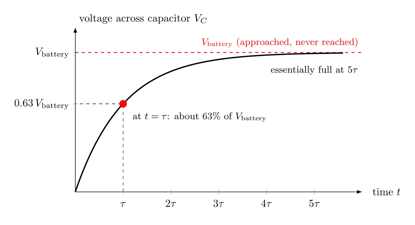
For a charging capacitor: the time constant is how long it takes for the charge to climb from zero to about 63% of its final value.
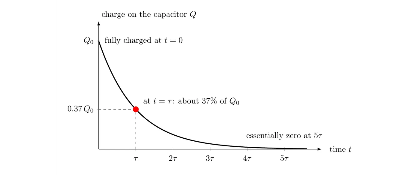
For a discharging capacitor: the time constant is how long it takes for the charge to fall from fully charged to about 37% of its starting value.
Rule of thumb: after roughly , the capacitor counts as fully charged or fully discharged (over 99% of the way there).
What changes τ: a bigger resistance means less current at any moment, so charge builds up more slowly. A bigger capacitance means more charge has to flow to reach the same potential difference. Either one makes τ bigger. The final charge, , doesn’t depend on at all. The resistor only controls how long it takes to get there.
Example: a 50 μF capacitor charges through a 40 kΩ resistor from a 9.0 V battery.
The final charge is C. After 2.0 s the capacitor holds about 63% of that, roughly C, and after about 10 s () it’s essentially full. Swap in an 80 kΩ resistor and τ doubles to 4.0 s, but the final charge is still C.
Measuring τ in the lab: charge the capacitor fully, then let it discharge through a known resistor while you read a voltmeter across the capacitor at regular times (a phone video of the meter works well). The time it takes the voltage to fall to 37% of its starting value is τ. For example, if the voltage falls from 10.0 V to 3.7 V in 4.7 s through a 47 kΩ resistor, then s and F, which is 100 μF.
Charging Behavior
When you drop an uncharged capacitor into a circuit with a battery and a resistor:
Initial State (t = 0)
Right after the circuit closes:
- An uncharged capacitor acts like a wire (a short circuit).
- Current is at its maximum: .
- Voltage across the capacitor is zero: .
- Charge on the capacitor is zero: .
During Charging
As it charges:
- Charge on the plates goes up.
- Voltage across the capacitor goes up.
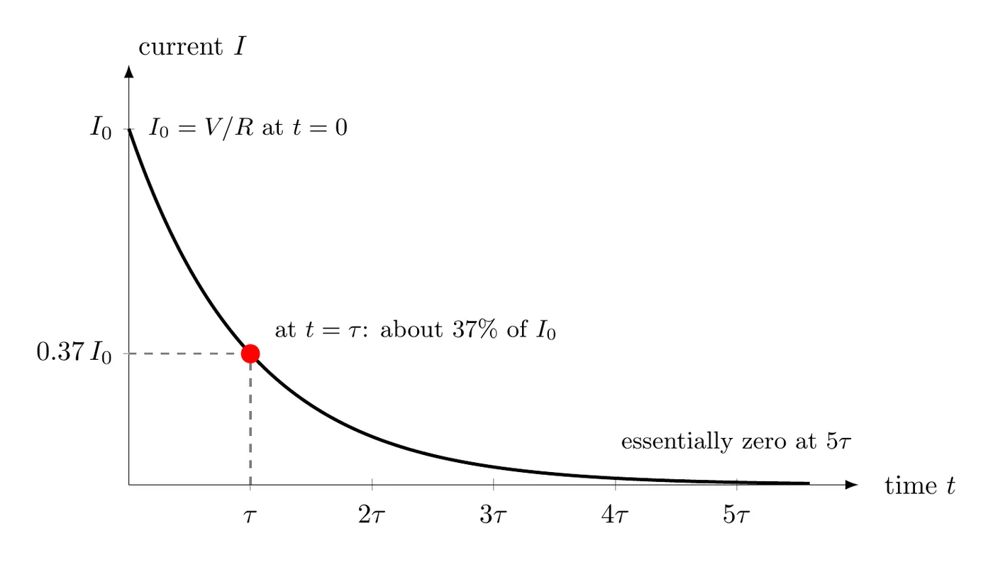
- Current in the circuit goes down.
- Electric potential energy stored in the capacitor goes up.
Why the current drops: by the loop rule, at every instant. As charge builds up, grows, which leaves less potential difference for the resistor, so the current gets smaller. Less current means charge arrives more slowly, which is why the charging curve flattens out instead of rising at a steady rate. For example, with a 12 V battery and a 3.0 kΩ resistor, the current starts at mA. When the capacitor reaches 9.0 V, the resistor only has 3.0 V across it, and the current is down to 1.0 mA. When reaches , nothing is left to push current through the resistor, and the current stops.
All of these ease asymptotically toward their steady-state values.
Final State (t → ∞)
After a long time (several time constants):
- The capacitor is fully charged.
- Voltage across the capacitor matches the battery voltage: .
- Current in the circuit is zero: .
- Charge on the capacitor is at its max: .
- The capacitor now acts like an open circuit (no current gets through).
Discharging Behavior
When a charged capacitor gets disconnected from the battery and drains through a resistor:
Initial State (t = 0)
Right when discharge starts:
- The capacitor has its maximum charge: .
- Voltage across it is at its max: .
- Current starts flowing out of the capacitor through the resistor.
- Initial current: .
- Energy stored in the capacitor starts to drop.
During Discharging
As it discharges:
- Charge on the plates goes down.
- Voltage across the capacitor goes down.
- Current in the circuit goes down.
- Electric potential energy stored in the capacitor goes down.
Why it slows down: during discharge the capacitor acts as the battery for the rest of the circuit, so the current is . As charge leaves the plates, drops, so the current drops too, and the remaining charge drains more and more slowly.
Final State (t → ∞)
After a long time:
- Charge on the capacitor is zero: .
- Voltage across the capacitor is zero: .
- Current is zero: .
- All the stored energy has been burned off as heat in the resistor.
Here’s the charge on a discharging capacitor over time. The potential difference across it () and the current in its branch have the same shape: each starts at its maximum and falls toward zero. The stored energy falls even faster, since both and in are shrinking.
Steady-State Approximation
Once you’re well past the time constant (, usually ), you can model the capacitor and its branch using steady-state conditions:
- After charging for a long time: treat the capacitor as an open circuit (no current in its branch). Its potential difference is whatever the rest of the circuit puts across that branch (see the example below).
- After a full discharge: treat the capacitor as having zero voltage and zero charge.
Example (a capacitor in one branch): a 12 V battery, a switch , and kΩ are in series with two parallel branches. One branch is kΩ. The other is kΩ in series with an uncharged 50 μF capacitor. The switch is closed at .
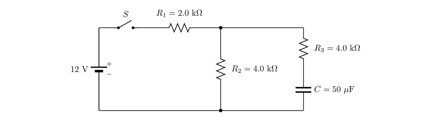
Right after the switch closes: the uncharged capacitor acts like a wire, so the capacitor branch is just . and in parallel make 2.0 kΩ, and the whole circuit is kΩ:
That leaves V across the branches, so mA, and .
After a long time: the capacitor is fully charged and acts like an open circuit, so , and and are simply in series:
With no current in , there’s no potential difference across it, so the capacitor has the same potential difference as : V, not the full 12 V.
Then the switch is opened: the battery and are cut off, and the capacitor discharges through and , which are now in series with it. The time constant is s, and the discharge starts with a current of mA. After 0.40 s, about 37% of the charge is left, roughly C.
Practice Problems
1. Three capacitors ( μF, μF, μF) are wired in series. Find the equivalent capacitance.
2. Take those same three capacitors and wire them in parallel. Find the equivalent capacitance.
3. An RC circuit has a resistor Ω and a capacitor μF.
- (a) Find the time constant.
- (b) If the capacitor starts uncharged and gets connected to a battery, how long until it hits 63% of its final charge?
4. A capacitor is charging in an RC circuit with time constant s. The battery is 12 V.
- (a) What’s the voltage across the capacitor right after the circuit closes?
- (b) What’s the voltage across it after a very long time?
- (c) Estimate the voltage across it at s.
5. Two capacitors, μF and μF, are wired in series with a battery. If the charge on is μC, what’s the charge on ?
6. In an RC circuit, right after you close the switch to charge an uncharged capacitor, what’s the current through the resistor if the battery is 9.0 V and the resistance is 3.0 kΩ?
7. A charged capacitor ( μF, charged to 20 V) discharges through a resistor ( kΩ).
- (a) What’s the initial current?
- (b) What’s the time constant?
- (c) Roughly what percentage of the charge is left after s?
8. Sketch rough graphs of (a) voltage across the capacitor vs. time and (b) current through the circuit vs. time for a charging RC circuit.
Solutions
1. For capacitors in series:
Answer: the equivalent capacitance is 2.0 μF, smaller than the smallest capacitor, just like you’d expect.
2. For capacitors in parallel:
Answer: the equivalent capacitance is 22 μF.
3.
- Find the time constant:
Answer: the time constant is 1.0 s.
- By definition, the time constant is exactly how long it takes to reach 63% of the final charge.
Answer: it takes 1.0 s (one time constant).
4.
- Right after closing (), an uncharged capacitor acts like a wire:
Answer: V.
- After a very long time (steady state), the capacitor is fully charged up to the battery voltage:
Answer: V.
- At s, the capacitor is at about 63% of its final voltage:
Answer: about 7.6 V.
5. By charge conservation, series capacitors carry the same charge on their plates:
Answer: μC.
6. At , the uncharged capacitor acts like a wire (zero resistance), so the initial current is:
Answer: the initial current is 3.0 mA.
7.
- Initial current when discharge kicks off:
Answer: the initial current is 0.40 mA.
- Time constant:
Answer: the time constant is 0.50 s.
- At s , the charge falls to about 37% of its starting value.
Answer: about 37% of the charge is left.
8.
(a) Voltage across the capacitor vs. time (charging):
(b) Current through the circuit vs. time (charging):
Common Mistakes
- Flipping the series/parallel rules for capacitors. Remember capacitors are the opposite of resistors. In series, use reciprocals. In parallel, just add.
- Forgetting series capacitors share the same charge. That’s a charge conservation thing. Each capacitor in series stores the same charge, not the same voltage.
- Mixing up the time constant with the charging time. The time constant is when the capacitor hits 63% charge (or 37% during discharge), not fully charged. Full charging takes about .
- Wrong initial conditions. At , an uncharged capacitor acts like a wire (zero voltage, maximum current). Don’t assume it starts out with voltage on it.
- Wrong final conditions. After a long time, a fully charged capacitor acts like an open circuit (maximum voltage, zero current). No current flows through a fully charged capacitor in DC steady state.
- Thinking capacitors always block current. Capacitors only block current in DC steady state once they’re fully charged. While charging or discharging, current does flow.
- Bad steady-state analysis. In DC steady state, replace fully charged capacitors with open circuits (a break in the wire). They won’t let current through.
- Unit slips with the time constant. Keep resistance in ohms and capacitance in farads so time comes out in seconds. Watch the prefixes (μF, kΩ, and so on).
- Forgetting direction matters for discharge. During discharge, current flows from the positive plate through the resistor to the negative plate, the opposite of the charging direction.
- Reaching for the transient formulas. The boundary statement says you’re not expected to use the exponential time-dependent equations. Stick to initial states, final states, and qualitative behavior.
- Misreading 63% and 37%. Those are the approximate values for one time constant. They come from and , but you don’t have to crunch exponentials, just know the benchmarks.
- Comparing the wrong capacitors. In parallel, every capacitor has the same voltage. In series, every one has the same charge. Use whichever equality fits the problem.