

3.5 - Compound Direct Current (DC) Circuits
Series and Parallel Connections
Circuit elements can be wired in series, in parallel, or in some mix of both.
Series Connection
A series connection means any charge passing through one element has to go through all the elements in that connection, because there’s no other route available.
Key property: the current in every element in series is the same.
Parallel Connection
A parallel connection means charges can take one of two or more paths.
Key property: the potential difference across each path is the same.
How to tell them apart on a schematic: two elements are in series if they’re connected end to end with no junction between them, so nothing branches off and all the charge has to go through both. Two elements are in parallel if each end of one connects directly to an end of the other, so both sit between the same two junctions. Some pairs are neither (for example, two resistors in different branches of a bigger network).
Equivalent Resistance
You can treat a whole group of resistors as if it were a single resistor with an equivalent resistance .
Resistors in Series
For resistors in series, the equivalent resistance is just the sum of the individual resistances:
Why: in series, charges have to pass through each resistor one after another, hitting each resistance in turn. The total opposition to current just adds up.
Resistors in Parallel
For resistors in parallel, the inverse of the equivalent resistance equals the sum of the inverses of the individual resistances:
Why: adding parallel resistors gives charges more paths to choose from, so the equivalent resistance of the group actually drops. More paths means less overall resistance.
Shortcut for just two resistors in parallel:
On the equation sheet these are and . The two-resistor shortcut isn’t on the sheet, but it comes straight from the parallel rule.
Adding a branch in parallel: adding a resistor in parallel always lowers , so an ideal battery puts out more total current. The branches that were already there don’t change, though: each one still has the full battery potential difference across it, so its current () stays the same. For example, one 12 Ω bulb across an ideal 6.0 V battery draws 0.50 A. Add a second identical bulb in parallel and drops to 6.0 Ω, so the battery supplies 1.0 A, but each bulb still has 6.0 V across it and 0.50 A through it, and it stays just as bright.
Worked Example: Reducing a Circuit Step by Step
A 24 V battery is connected to Ω. After , the circuit splits into two branches: one branch is Ω, and the other is Ω and Ω in series. Find the current in each resistor.
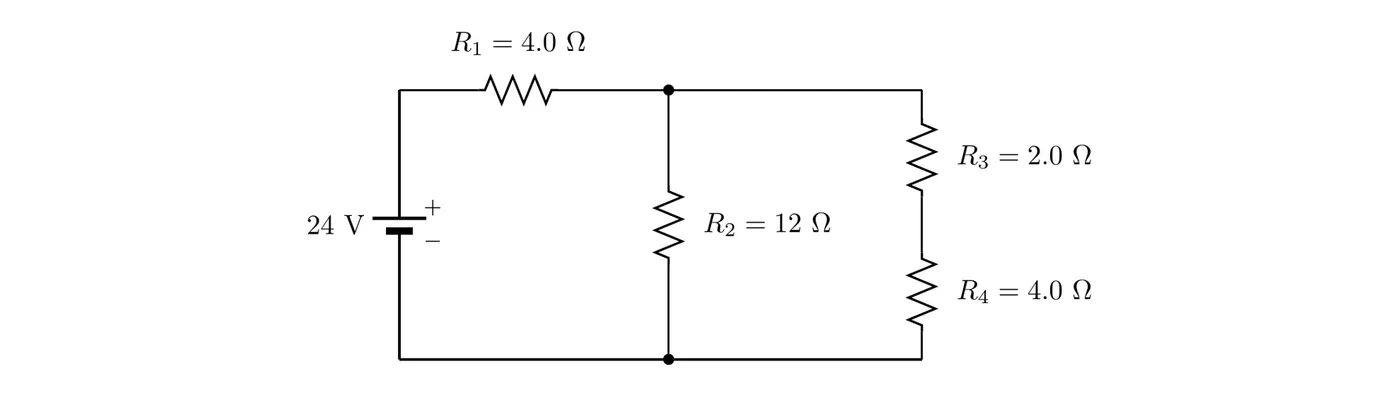
Step 1: start with the innermost group, the part farthest from the battery. and are in series (nothing branches off between them):
Step 2: that 6.0 Ω branch and connect the same two junctions, so they’re in parallel:
Step 3: the parallel group is in series with :
Step 4: now work back out. All of the battery’s current goes through :
That leaves V across both branches, since parallel branches share the same potential difference:
Answer: A, A, and A. Check: the branch currents add back up to the battery current, A. In the second branch, V and V, which add up to the 12 V across the branch.
Ideal vs. Non-Ideal Components
Ideal Wires
Ideal wires have basically no resistance.
- The resistance of good conductors (wires) can usually be ignored because it’s so much smaller than the other elements in the circuit.
- You can only ignore wire resistance if the circuit has other elements that do have resistance. If there’s nothing resistive in the circuit at all, you can’t ignore the wire resistance.
Example: a 2.0 m piece of copper wire ( Ω·m) with a diameter of 1.0 mm has a resistance of
In series with a 100 Ω resistor, that adds less than 0.05% to the total resistance, so ignoring it is safe. But connect the same wire straight across an ideal 1.5 V battery with nothing else in the loop, and the wire is the only resistance: A. Ignoring the wire here would mean dividing by zero. That’s why wire resistance can only be neglected when other elements in the circuit have resistance. (A real battery’s internal resistance would keep the current lower, but it would still be a dangerous short circuit.)
Ideal Batteries
Ideal batteries have basically no internal resistance.
The emf () is the potential difference a battery would deliver if it were ideal. It’s the potential difference you’d measure across the terminals when there’s no current flowing through the battery.
Non-Ideal Batteries (Internal Resistance)
Real batteries have some internal resistance (), which you can picture as a resistor sitting in series with an ideal battery.
When current flows through a non-ideal battery, the terminal voltage (the voltage across the battery terminals) comes out lower than the emf:
where:
- = voltage across the battery terminals (V)
- = emf of the battery (V)
- = current through the battery (A)
- = internal resistance of the battery (Ω)
That term is the voltage “lost” inside the battery to its own internal resistance.
This is a derived equation, so it isn’t on the equation sheet. It comes from the loop rule (3.6): going through the battery from − to +, you gain in the ideal part of the battery and then lose across the internal resistance. The equation also shows how emf is measured: with no current (), , so a voltmeter across a battery with nothing else connected reads the emf. The more current the battery delivers, the lower its terminal voltage.
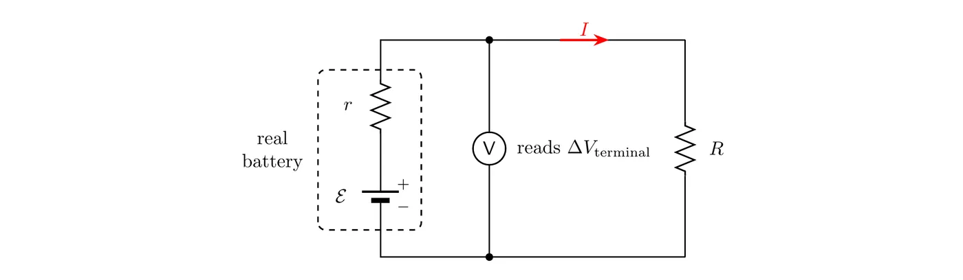
Example (lab): a voltmeter across a battery reads 6.00 V with nothing else connected. When the battery is connected to a lamp, the current is 0.800 A and the voltmeter reads 5.60 V. Find the internal resistance and the lamp’s resistance.
Answer: Ω, and the lamp is 7.00 Ω. The terminal voltage is the potential difference across the lamp, since the lamp is the only thing connected to the battery’s terminals.
Measuring Current and Voltage
Ammeters
Ammeters measure the current at a specific point in a circuit.
- How to connect it: in series with the element.
- Ideal ammeter: has zero resistance, so it doesn’t mess with the current it’s measuring.
- Non-ideal ammeter: has some resistance, which drops the current in the circuit a bit.
Voltmeters
Voltmeters measure the electric potential difference between two points in a circuit.
- How to connect it: in parallel with the element.
- Ideal voltmeter: has infinite resistance, so no charge flows through it.
- Non-ideal voltmeter: has finite resistance, so it draws a little current and affects the circuit.
Effect of Non-Ideal Meters
Non-ideal ammeters and voltmeters change the circuit they’re measuring:
- A non-ideal ammeter adds resistance in series, which lowers the current.
- A non-ideal voltmeter gives charges an extra parallel path, drawing current and possibly pulling down the very voltage you’re trying to read.
Example: two 10 kΩ resistors are in series with a 12 V battery, so each one has 6.0 V across it. A student checks one resistor with a cheap voltmeter whose own resistance is also about 10 kΩ. The meter and the resistor now form a parallel pair with less resistance than the resistor alone, so that part of the circuit gets less than half of the 12 V, and the meter reads less than 6.0 V. A good voltmeter has a resistance far larger than anything it’s connected across, so it barely changes the circuit.
Practice Problems
1. Three resistors ( Ω, Ω, Ω) are wired in series to a 12 V battery.
- (a) Find the equivalent resistance.
- (b) Find the current through each resistor.
- (c) Find the voltage drop across .
2. Take those same three resistors and wire them in parallel to a 12 V battery instead.
- (a) Find the equivalent resistance.
- (b) Find the total current from the battery.
- (c) Find the current through .
3. A battery has an emf of 9.0 V and internal resistance of 0.50 Ω. When it’s connected to a circuit, it delivers 2.0 A. What’s the terminal voltage?
4. Two resistors, Ω and Ω, are in parallel. That combo is then wired in series with a Ω resistor and a 24 V battery.
- (a) Find the equivalent resistance of the whole circuit.
- (b) Find the total current from the battery.
- (c) Find the voltage across the parallel combination.
5. Explain why adding more resistors in parallel drops the total resistance, while adding more in series raises it.
6. A student wants to measure the current through a 100 Ω resistor. Her ammeter has a resistance of 5 Ω. Describe, roughly, how this non-ideal ammeter throws off her measurement.
Solutions
1.
- For series resistors:
Answer: the equivalent resistance is 55 Ω.
- In series the current is the same through all of them:
Answer: each resistor carries 0.22 A.
- Use Ohm’s law for :
Answer: the voltage drop across is 3.3 V.
2.
- For parallel resistors:
Answer: the equivalent resistance is 5.0 Ω, which is smaller than any single resistor in the group.
- Total current from the battery:
Answer: the total current is 2.4 A.
- In parallel, each resistor sees the full voltage:
Answer: the current through is 0.40 A.
3. Use the terminal voltage equation:
Answer: the terminal voltage is 8.0 V. The battery “loses” 1.0 V inside itself.
4.
- First find the equivalent resistance of the parallel pair:
Now add that in series with :
Answer: the equivalent resistance is 22 Ω.
- Total current:
Answer: the total current is 1.1 A.
- The voltage across :
Whatever’s left is across the parallel combination:
Answer: the voltage across the parallel combination is 13.1 V.
5.
Series: in a series connection, charges have to pass through each resistor one after the next, and each one adds its own opposition to the flow. The total resistance is the sum of them all, so tacking on another resistor pushes the total up.
Parallel: in a parallel connection, adding another resistor opens up another path for current. More paths make it easier for charges to get through the circuit. Since the charges can spread out and split up, the overall opposition to flow goes down. The equivalent resistance always ends up smaller than the smallest single resistor in the parallel network.
The math backs this up: adding positive terms to a plain sum makes it bigger (series), while adding positive terms to a sum of reciprocals makes the final equivalent resistance smaller than any of the individuals (parallel).
6. The ammeter has to go in series with the 100 Ω resistor. An ideal ammeter would add zero resistance, but this one tacks on 5 Ω.
That bumps the total resistance from 100 Ω up to 105 Ω, a 5% increase. By Ohm’s law, more resistance at a fixed voltage means less current. So the ammeter reads a current that’s lower than what would actually flow with an ideal ammeter.
The reading comes out roughly 5% below the true value. The ammeter’s own resistance ends up shrinking the exact thing it’s supposed to measure.
Common Mistakes
- Adding parallel resistances straight up. For parallel resistors you have to add the reciprocals and then flip the result. Don’t just add the resistances together.
- Forgetting the final flip. After you get , you still have to invert it to find .
- Thinking parallel resistance is bigger. The equivalent resistance of parallel resistors is always less than the smallest single resistor.
- Mixing up the current and voltage rules. In series the current is the same everywhere. In parallel the voltage is the same across each branch.
- Ignoring internal resistance. When a battery has internal resistance, the terminal voltage is below the emf whenever current flows. Use .
- Placing meters wrong. Ammeters go in series (to read the current through). Voltmeters go in parallel (to read the voltage across).
- Assuming everything is ideal. Real ammeters have a small but nonzero resistance, and real voltmeters have a large but not infinite resistance. Those non-ideal traits shift your measurements.
- Misapplying equations to mixed circuits. For circuits with both series and parallel parts, simplify one step at a time, starting with the innermost group (the part farthest from the battery), whether that’s a series pair or a parallel pair. Replace it with its equivalent resistor, redraw, and repeat until one resistor is left.
- Sign errors with internal resistance. The voltage drop from internal resistance works against the emf, so you subtract it: , not added.