

3.4 - Dielectrics
Introduction to Dielectric Materials
A dielectric is an insulating material you stick between the plates of a capacitor. Unlike in a conductor, the charges in a dielectric can’t roam free. Instead, the material becomes polarized when you put it in an external electric field.
How it differs from a plain capacitor:
- Regular capacitor: air (or vacuum) between the plates.
- Dielectric capacitor: an insulating material between the plates.
The dielectric changes how the capacitor behaves, affecting its capacitance, its electric field, and how much energy it stores.
The Dielectric Constant (κ)
Every dielectric material has a characteristic property called the dielectric constant, written with the Greek letter kappa (κ).
The Definition
The dielectric constant is a dimensionless number describing how much the material knocks down the electric field compared to vacuum:
where:
- (kappa) = dielectric constant (dimensionless).
- = permittivity of the material (C²/(N·m²)).
- C²/(N·m²) = permittivity of free space.
Rearranged to get the material’s permittivity:
Example: water has , so its permittivity is C²/(N·m²). Inside a material, replaces in Gauss’s law, so the field of a charge sitting in water is 80 times weaker than in vacuum.
Common Dielectric Constants
Material | Dielectric Constant (κ) |
Vacuum | 1.00000 (by definition) |
Air | 1.00059, basically 1.0 |
Paper | 3.7 |
Glass | 4 to 6 |
Neoprene rubber | 6.7 |
Water | 80 |
Oil | 2 to 5, depending on the type |
Important: since for every material, a dielectric always bumps the capacitance up compared to vacuum.
On the AP test: they’ll give you the dielectric constant if you need a specific value, since there’s no big table of them on the formula sheet.
What Dielectrics Do to the Electric Field
Slide a dielectric between the plates and the material polarizes. That polarization sets up an internal field that pushes back against the external field.
The Field Gets Weaker
The field inside the dielectric is reduced compared to what it would be without:
where:
- = field with the dielectric (V/m).
- = field without the dielectric (V/m).
- = dielectric constant.
Flipped around (to find the dielectric constant from the fields):
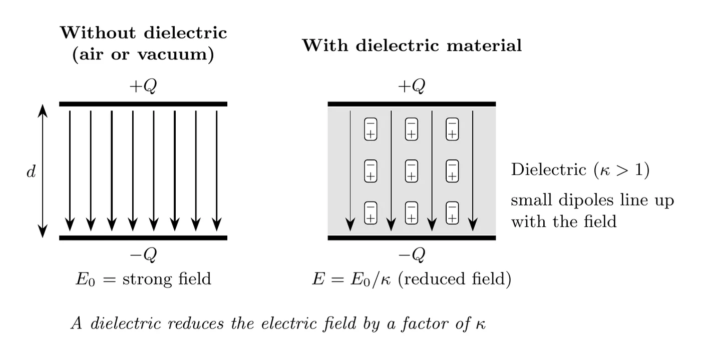
What’s physically happening:
The dielectric molecules polarize, meaning their positive and negative charges shift apart a little bit within each molecule. Those induced dipoles generate their own field that opposes the applied one, so the total field comes out smaller.
Two ways a dielectric polarizes:
- Polar molecules (like water) are already tiny dipoles. Normally they point every which way, but in a field they tend to rotate and line up with it. That’s why water’s is so large.
- Nonpolar molecules get stretched: the field pulls each molecule’s electron cloud one way and its nucleus the other way, making an induced dipole.
Either way, no charge leaves its molecule. That’s the difference from a conductor, where electrons travel freely through the whole material.
Where the opposing field comes from: inside the material, the and ends of neighboring dipoles cancel out. At the surfaces they don’t: a thin layer of negative charge shows up on the face next to the positive plate, and a layer of positive charge on the face next to the negative plate. Those layers act like a weaker capacitor pointing the other way, so their field is opposite to the plates’ field, and the total field is what’s left over:
For , the induced layers cancel of the plates’ charge density, so the field drops to of .
One condition: is for an isolated capacitor (charged, then disconnected), so the charge on the plates can’t change. If a battery stays connected, the field ends up the same as before. See “Isolated vs. Connected to a Battery” near the end of this page.
What Dielectrics Do to the Capacitance
Adding a dielectric raises the capacitance.
Capacitance with a Dielectric
where:
- = capacitance with the dielectric (F).
- = capacitance without it (F).
- = dielectric constant.
Written out with the geometry:
where:
- = area of the plates (m²).
- = separation distance (m).
How It Ties Back to the Capacitor Formula
From the previous topic, a plain air-filled capacitor has:
That’s just the dielectric formula with , since that’s air’s value.
The general idea:
- A regular capacitor is just a dielectric capacitor with .
- A dielectric with boosts how much charge you can store.
Measuring κ in the Lab
You can find a material’s dielectric constant from a graph. Stack identical sheets of the material (each of thickness ) between two metal plates of area , so , and measure with a capacitance meter for to 5. Since , a graph of vs. should be a straight line through the origin with slope .
Sample data (plates of area 0.040 m², paper sheets 0.10 mm thick):
Sheets | (mm) | (m⁻¹) | (nF) |
1 | 0.10 | 13.1 | |
2 | 0.20 | 6.7 | |
3 | 0.30 | 4.3 | |
4 | 0.40 | 3.2 | |
5 | 0.50 | 2.6 |
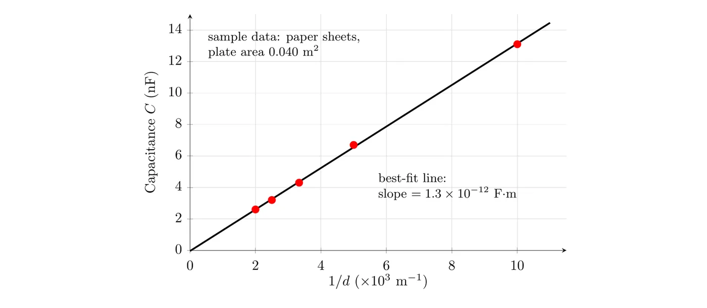
The best-fit line has a slope of about F·m (the nF and the m⁻¹ units combine to F·m), so:
That matches paper’s dielectric constant in the table above. Using the slope instead of a single data point averages out the scatter in the measurements.
Modified Gauss’s Law for Dielectrics
When you use Gauss’s Law inside a dielectric, you have to account for the material’s permittivity.
General Form
Substituting :
For a uniform field, which is what you get in a parallel plate capacitor:
Side by side:
- Vacuum or air:
- Dielectric:
That extra in the denominator is exactly the field reduction the material causes.
Compound Dielectrics
When a capacitor has more than one dielectric material in it, you need an effective capacitance. How they’re arranged tells you whether to treat them like capacitors in parallel or in series.
Configuration 1: Parallel Dielectrics (Side by Side)
When the dielectrics sit side by side, the field lines pass through each region separately. That’s just like capacitors in parallel.
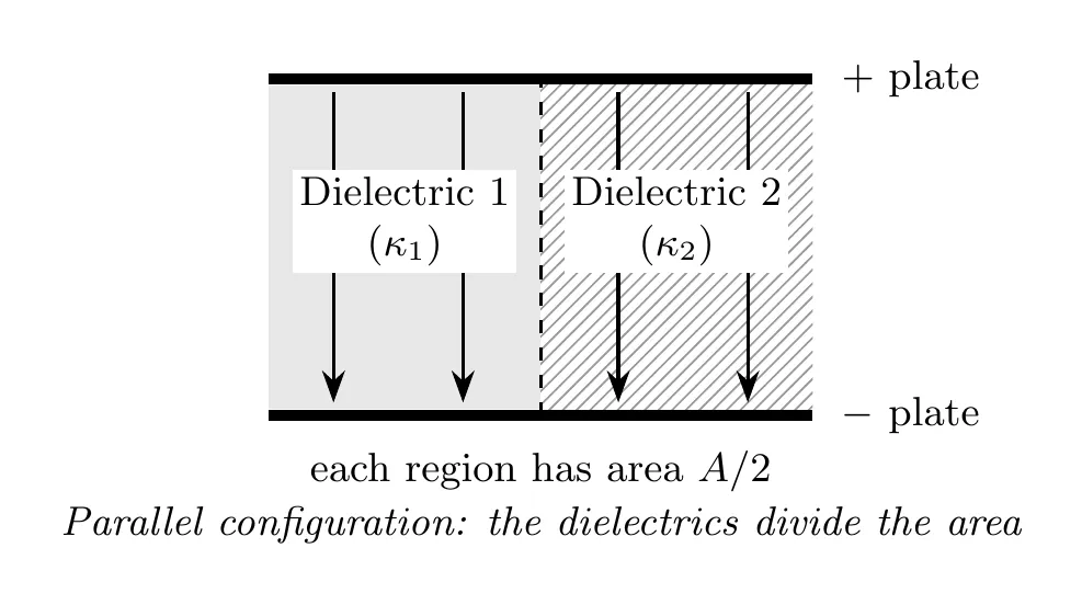
Effective capacitance (for equal areas):
where is the capacitance with no dielectric at all.
General form (for any area fractions and where ):
The way to think about it: each dielectric acts like its own separate capacitor, and they combine the way parallel capacitors do.
Configuration 2: Series Dielectrics (Stacked)
When the dielectrics are stacked along the field direction, the field lines have to pass through both materials one after another. That’s like capacitors in series.
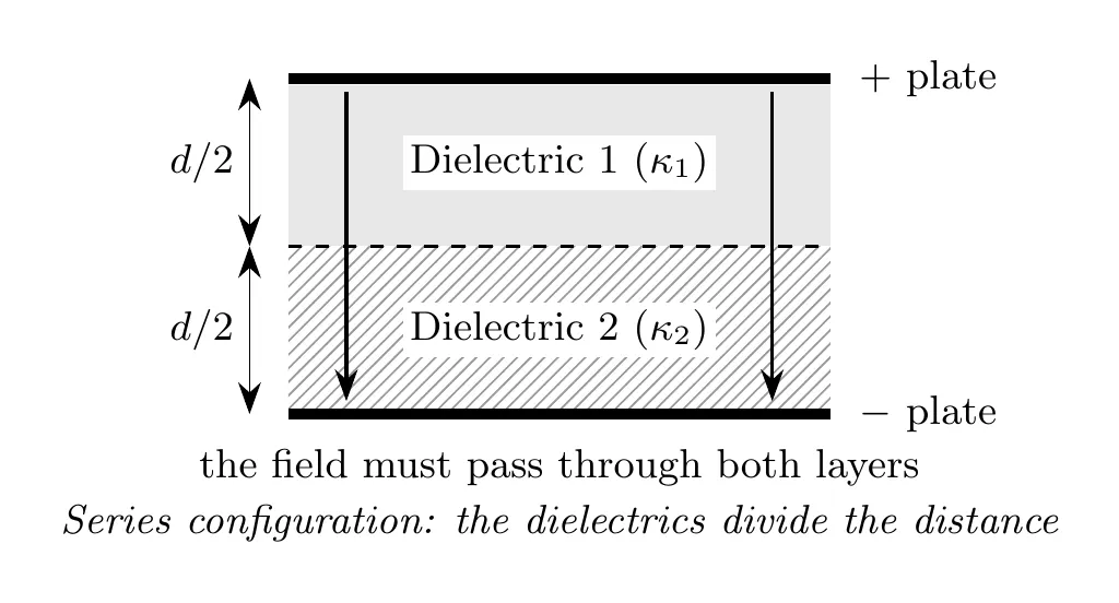
Effective capacitance (for equal thicknesses):
General form (for arbitrary thickness fractions):
It’s no harder than the equal case. Treat each layer as its own parallel-plate capacitor with the full area and its own thickness ( and ), then combine them in series:
With , this simplifies to the equal-thickness formula above.
The way to think about it: the total voltage drop is the sum of the drops across each layer, which is the hallmark of a series combination.
The Small Gap Scenario
A common twist: most of the gap is filled with one dielectric, but there’s a thin sliver of air.
Example: the total gap is 9 mm, with 3 mm of air and the rest filled with paper.
- This is a series setup, since the field has to cross both.
- Even a tiny air gap moves the capacitance noticeably, because air has .
With numbers (paper has ): the paper layer is 6 mm thick and the air layer is 3 mm thick. Compare with for an all-air gap:
Filling the whole 9 mm with paper would give , so the 3 mm air gap cuts the capacitance roughly in half.
Connection to Circuit Analysis
The compound dielectric formulas come straight from the rules for combining capacitors in circuits.
Capacitors in parallel:
Capacitors in series:
Those same rules apply when you treat each dielectric region as its own capacitor.
Example Problem: Cylindrical Capacitor with Oil
Problem:
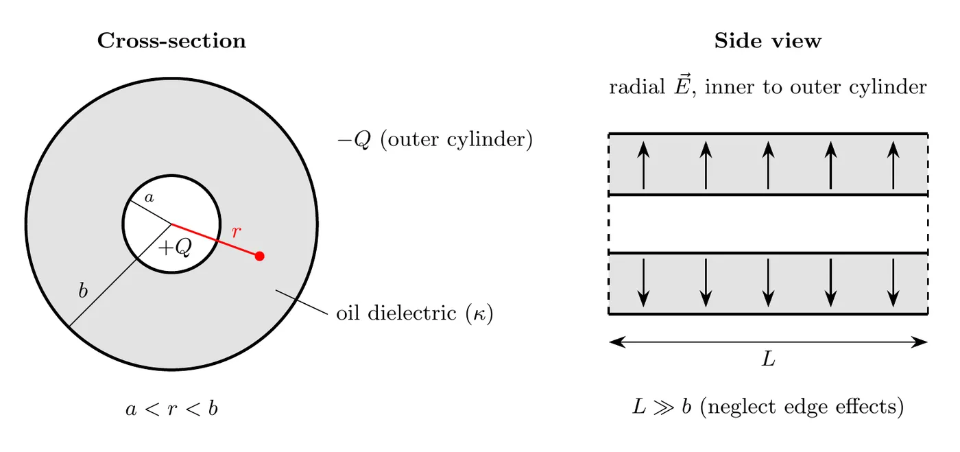
A capacitor is made of two coaxial conducting cylindrical shells with inner radius and outer radius . The length is much bigger than , so edge effects don’t matter. The space between the cylinders is filled with oil that has dielectric constant .
Both cylinders start out uncharged. A battery then puts charge on the inner cylinder and on the outer one.
Find:
(a) The electric field in the oil, for .
(b) The potential difference between the cylinders.
(c) The capacitance of the system.
Solution
(a) Electric Field in the Oil
Apply Gauss’s Law for dielectrics:
Pick a Gaussian surface: a coaxial cylinder of radius (with ) and length .
By symmetry, the field is radial and has the same magnitude everywhere at radius :
The area of the Gaussian surface (just the curved side of the cylinder):
So:
Solve for :
Answer (a): the field at radius in the oil is:
Notice the field goes like here, which is the cylindrical geometry, not like you’d get with spherical geometry.
(b) Potential Difference
Get the potential difference by integrating the field:
To make the algebra cleaner, flip the limits and drop the negative sign:
Substitute in the expression for :
Pull out the constants:
The integral of is :
Evaluate it:
Use the log property :
Since , that comes out negative. Take the absolute value, or just write it as :
Answer (b): the potential difference is:
(c) Capacitance
Use the definition of capacitance:
Substitute the result from part (b):
The cancels out:
Answer (c): the capacitance is:
Physical sanity check:
- Bigger gives bigger ✓
- Bigger gives bigger ✓
- Bigger (a wider gap) gives smaller ✓
With numbers: a coaxial cable has an inner conductor of radius 0.50 mm, an outer conductor of radius 2.0 mm, and polyethylene () between them. For a 10 m length:
That’s about 92 pF per meter of cable.
Summary of Key Formulas
Quantity | Formula | Notes |
Dielectric constant | Dimensionless | |
Material permittivity | C²/(N·m²) | |
Field with dielectric | Field gets weaker | |
Capacitance with dielectric | Capacitance gets bigger | |
Parallel plate with dielectric | The standard formula | |
Parallel dielectrics | Side by side | |
Series dielectrics | Stacked |
Comparison Table: Vacuum vs. Dielectric
Property | Vacuum/Air () | With Dielectric () |
Electric field | (smaller) | |
Capacitance | (bigger) | |
Voltage (constant Q) | (smaller) | |
Energy (constant Q) | (smaller) |
About the energy: when the charge is fixed and you slide a dielectric in, the energy drops, because the dielectric gets pulled into the capacitor by attractive forces. The system does the work.
Isolated vs. Connected to a Battery
The table above is for an isolated capacitor: it was charged and then disconnected, so can’t change. That’s the case where the field drops by a factor of . If the capacitor stays connected to a battery, the battery holds fixed instead, and the results change:
Property | Isolated ( fixed) | Connected to a battery ( fixed) |
Capacitance | ||
Charge | (same) | (the battery adds charge) |
Voltage | (same) | |
Electric field | (same, since ) | |
Energy |
Why the field stays the same when connected: the dielectric’s induced charge still opposes the field, but the battery pushes extra charge onto the plates until is back where it started.
Example: an air-filled capacitor with pF and plates 2.0 mm apart is charged to 120 V. A slab with is then slid in to fill the gap, so pF.
Case 1, disconnected first. stays at C. Then V, and V/m, a quarter of the original V/m. The energy drops from J to J.
Case 2, still connected. The battery keeps V, so C, four times the original charge. The field stays V/m, and J, four times the original energy.
Common Mistakes
- Losing track of where κ goes. For capacitance, lives in the numerator: . For the electric field from Gauss’s Law, lives in the denominator: . Don’t flip them.
- Thinking dielectrics reduce capacitance. They always increase it, since . They shrink the field but boost the charge storage.
- Forgetting that the integral of 1/r is ln(r). When you integrate , you get , NOT or any power of . This one is essential for cylindrical geometry problems.
- Mixing up the parallel and series dielectric formulas. Parallel means the dielectrics split the area (side by side). Series means they split the distance (stacked). Different formulas, not interchangeable.
- Trying to memorize dielectric constants. There’s no comprehensive table on the formula sheet, so any specific you need will be handed to you in the problem. Don’t waste time memorizing them.