

5.3 - Torque
Introduction: The Rotational Equivalent of Force
Torque is the rotational version of force. Just as a force causes linear acceleration, a torque causes angular acceleration.
When a force acts on a rigid system at some distance from the axis of rotation, and it isn’t aimed straight toward or away from the axis, it creates a torque.
The key idea: torque measures the “twisting effect” of a force, meaning its ability to cause rotation.
Lever Arm (Moment Arm)
The lever arm, also called the moment arm, is the perpendicular distance from the axis of rotation to the line of action of the force.
Symbol: (sometimes written as ). Units: meters (m).
A way to picture it: imagine using the force vector as a compass to draw a circle. The axis of rotation is where you plant the compass point, and the lever arm is the radius of that circle.
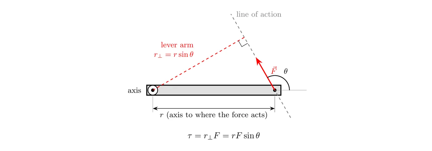
Torque Diagrams (Rigid Body Diagrams)
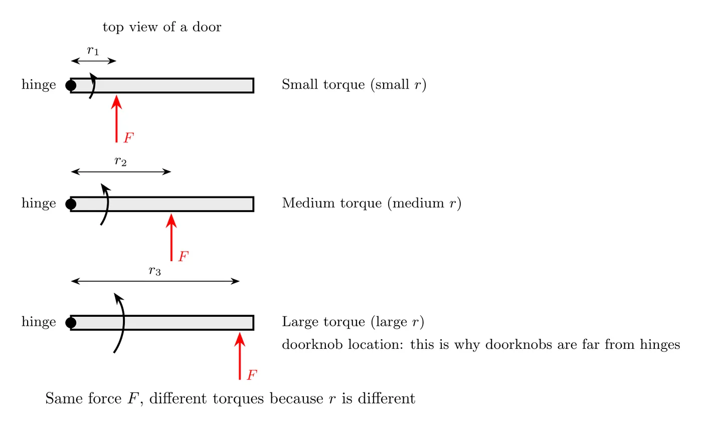
Unlike free body diagrams, where the forces are drawn at the center of mass, torque diagrams put the forces at their actual points of application relative to the axis of rotation.
Why? Because where the force is applied matters. The same force creates different torques depending on where it acts.
These are sometimes called rigid body diagrams, because they show the extended body rather than just a point mass.
On the AP exam, these are called force diagrams. A force diagram works like a free body diagram: each force gets an arrow showing its direction and its size compared with the other forces (a force twice as big gets an arrow about twice as long). What’s new is that each arrow starts where that force actually acts, so the diagram shows the location of every force relative to the axis of rotation. You’ll often draw both: a free body diagram to analyze the linear motion and a force diagram to analyze the torques.
The Mathematical Definition of Torque
Torque is defined with the cross product of the position vector and the force vector:
where:
- = torque (the Greek letter tau), in N·m
- = position vector from the axis to the point where the force is applied (m)
- = force vector (N)
- = the cross product
The cross product multiplies two vectors and gives you a vector result.
In general, the cross product of any two vectors and is a vector with magnitude
where is the angle between the two vectors when they’re drawn tail to tail.
- Direction: perpendicular to both and , so it’s normal to the plane the two vectors lie in. The right-hand rule (below) tells you which of the two perpendicular directions it is.
- Order matters: , the same size but the opposite direction. Always write , with first.
- Parallel vectors: if or , the cross product is zero.
Magnitude of Torque
The magnitude of the torque is:
where:
- = magnitude of the torque (N·m)
- = distance from the axis to the point where the force is applied (m)
- = magnitude of the force (N)
- = angle between and
Alternative forms:
where:
- is the lever arm, the perpendicular distance from the axis to the force’s line of action.
- is the component of the force perpendicular to .
Maximum and Minimum Torque
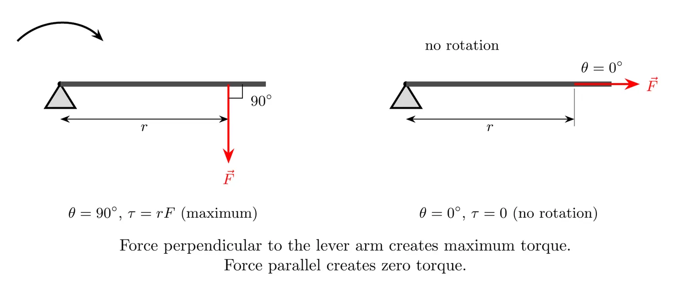
Maximum torque happens when the force is perpendicular to the position vector ():
Minimum (zero) torque happens when the force is parallel to the position vector ( or ):
The read: pushing directly toward or away from the axis creates no rotation at all, just compression or tension.
Why Doorknobs Are Where They Are
A practical application: doorknobs sit as far as possible from the hinges (the axis of rotation) because of
For the same force :
- A larger (far from the hinge) gives a larger torque, so the door is easier to open.
- A smaller (near the hinge) gives a smaller torque, so the door is harder to open.
The design principle: to get more torque out of less force, maximize the lever arm.
More examples:
- Wrenches have long handles to boost torque.
- Wheelbarrows put the handles far from the wheel.
- Seesaws work best with the riders far from the pivot.
Direction of Torque (The Right-Hand Rule)
Since torque comes from a cross product, it’s a vector with a direction.
The Right-Hand Curl Rule
The steps:
1. Point your fingers in the direction of , from the axis toward the force.
2. Curl your fingers toward the direction of .
3. Your thumb points in the direction of .
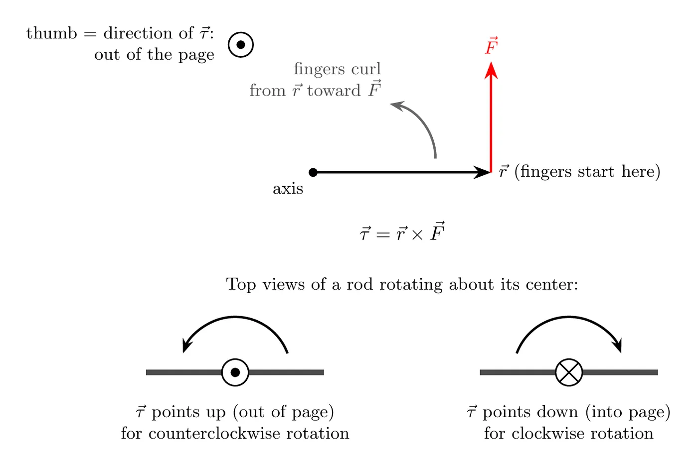
Because is perpendicular to both and , when those two vectors lie in the plane of the page, the torque points straight out of the page or straight into it:
- Out of the page: the force tends to turn the system counterclockwise.
- Into the page: the force tends to turn the system clockwise.
That’s why, for rotation about one axis, you can treat torque as a single number with a sign, which is what the sign convention below does.
Sign Convention (Simplified)
For problems in a plane (2D rotation):
- Counterclockwise rotation gives a positive torque (+).
- Clockwise rotation gives a negative torque (−).
A memory aid: “righty tighty, lefty loosey.” Turning a screw clockwise (right) tightens it, and turning it counterclockwise (left) loosens it. The phrase doesn’t map perfectly onto our sign convention, but it helps you keep the rotation directions straight.
Example Problem: Drawbridge
Problem: It takes a torque of 5000 N·m to raise a drawbridge. The cable pulling the bridge makes an angle with the bridge, and it’s attached 6.0 m from the pivot (the hinge).
- What cable tension is needed to produce this torque?
- Would it be easier to raise the drawbridge if the angle were larger or smaller?
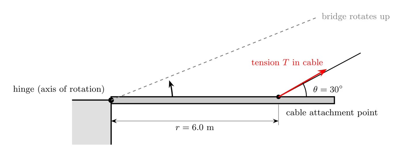
Part (a): Finding the Tension
Step 1: Write the torque equation
Here, the force making the torque is the tension :
Step 2: Solve for the tension
Step 3: Substitute the values
Given:
N·m, m, .
Answer: the tension has to be about 1700 N (1667 N to be precise).
Note: that’s the magnitude of the full tension force, not just a component. The term accounts for the fact that only the perpendicular part of the tension contributes to the torque.
Part (b): The Effect of Changing the Angle
The question: would it be easier (need less tension) if were larger or smaller?
Look at the equation:
and have an inverse relationship through :
- As increases, decreases, so it gets easier.
- As decreases, increases, so it gets harder.
Since grows as goes from 0° to 90°, increasing decreases the tension, which makes it easier to raise.
Answer: it would be easier if the angle were larger.
Verification with Numbers
Try :
Comparing:
- At : N.
- At : N.
Sure enough, increasing dropped the required tension. ✓
The read: when the cable pulls more perpendicular to the bridge (a larger ), more of the tension goes into producing rotation, so you need less total tension.
The optimal angle is , with the cable perpendicular to the bridge, where and the tension is at its minimum.
Example Problem: Net Torque from a Force Diagram
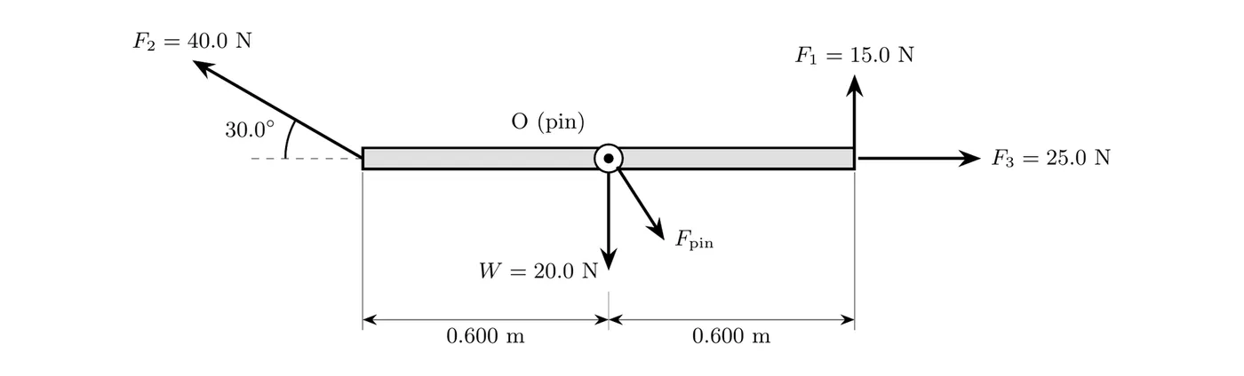
Problem: A uniform 2.00 kg rod, 1.20 m long, turns on a frictionless pin through its center, O. The force diagram shows every force on the rod at the instant it’s horizontal: N straight up at the right end, N at the left end pointing up and to the left at 30.0° above the rod, N at the right end pulling straight along the rod, the rod’s weight N (using m/s²), and the force from the pin. Find the torque from each force about O and the net torque. Take counterclockwise (out of the page) as positive.
Solution
Step 1: Forces at the axis. The weight acts at the center of mass, which is at O, and the pin pushes on the rod at O. Both have , so both make zero torque, no matter how big they are.
Step 2: The force along the rod. pulls straight along the rod, so its line of action passes through O. The angle between and is 0°, so .
Step 3: The perpendicular force. is perpendicular to the rod, 0.600 m from O, and it tends to turn the rod counterclockwise:
Step 4: The angled force. acts 0.600 m from O at 30.0° to the rod. Pulling up on the left end, it tends to turn the rod clockwise:
Check with the lever arm: extend ’s line of action. Its perpendicular distance from O is m, and N·m. Same answer.
Check with the cross product: put O at the origin with to the right and up. Then and N. Since and (out of the page):
The direction is into the page, which means clockwise.
Step 5: Add the torques.
Answer: the net torque about O is 3.0 N·m clockwise (into the page).
The read: the biggest force, , doesn’t make a torque of N·m, because only its component perpendicular to the rod, N, twists the rod. And , at 25.0 N, makes no torque at all. In 5.5/5.6 you’ll see that a net torque like this one gives the rod an angular acceleration.
Units of Torque
The SI unit is the newton-meter (N·m).
Dimensional analysis:
An important distinction: torque has units of N·m, and energy has units of joules (J), and mathematically 1 J = 1 N·m. But we don’t write torque in joules, because the two are conceptually different:
- Torque is a twisting effect (N·m).
- Energy is work done (J).
Always use N·m for torque, not J.
Summary of Key Formulas
Concept | Formula | Notes |
Torque (vector) | The cross product definition | |
Torque (magnitude) | The general formula | |
Maximum torque | When (perpendicular) | |
Zero torque | When or (parallel) | |
Alternative form | Using perpendicular components |
Common Mistakes
- Not checking your calculator mode. When you compute , make sure the calculator is in degree mode if is in degrees.
- Confusing torque with energy. Torque has units of N·m but it is not energy. Don’t write torque in joules.
- Measuring r incorrectly. is the distance from the axis of rotation to the point where the force is applied, not just any distance.
- Assuming every force creates torque. Forces applied right at the axis () create zero torque. Forces parallel to (pointing straight toward or away from the axis) also create zero torque.
- Using the wrong angle. is the angle between and , not necessarily the angle the force makes with the horizontal or vertical.
- Forgetting that direction matters. Torque is a vector. Clockwise and counterclockwise torques have opposite signs, so account for direction when you add multiple torques.
- Putting forces at the center of mass in torque problems. For torque, draw the forces at their actual points of application, not at the center of mass.
- Thinking a larger angle always means more torque. Not true. Torque depends on , which peaks at . Past 90°, starts dropping.
- Confusing the lever arm with the object’s length. The lever arm is the perpendicular distance from the axis to the force, which can be shorter than the physical distance along the object.
- Missing the inverse relationship in part (b). In , increasing (the denominator) decreases . A lot of students wrongly think a bigger angle means more tension.
- Adding torques and forces together. Don’t mix them. Torques add with torques, and forces add with forces. They’re different quantities.
- Getting the clockwise/counterclockwise sign wrong. Be consistent. Pick a convention (counterclockwise as positive is standard) and stick with it through the whole problem.
- Forgetting the perpendicular component. Only the component of force perpendicular to makes torque. The parallel component contributes nothing.
- Using when the force isn’t perpendicular. That simplified formula only works when . Otherwise use .
- Not understanding why doorknobs sit far from hinges. This is a classic conceptual question. A larger means more torque for the same applied force, which makes the door easier to open.