

5.3 - Torque
The Rotational Analog of Force
Continuing the analogy between linear and rotational motion: just as force causes linear acceleration, torque causes angular acceleration.
Torque (, the Greek letter tau) is the rotational equivalent of force, the “twist” or “turning force” that causes objects to rotate. Not every force produces the same rotational effect, how effective a force is at causing rotation depends on how large it is (magnitude), where it’s applied (distance from the axis), and at what angle it’s applied (direction relative to the line from the axis to where it’s applied).
What Creates Torque
Torque only comes from the component of force that’s perpendicular to the radius (the line from the axis to where the force is applied). Forces parallel to the radius just pull or push along it, they don’t cause any rotation. Only the perpendicular component actually twists something.
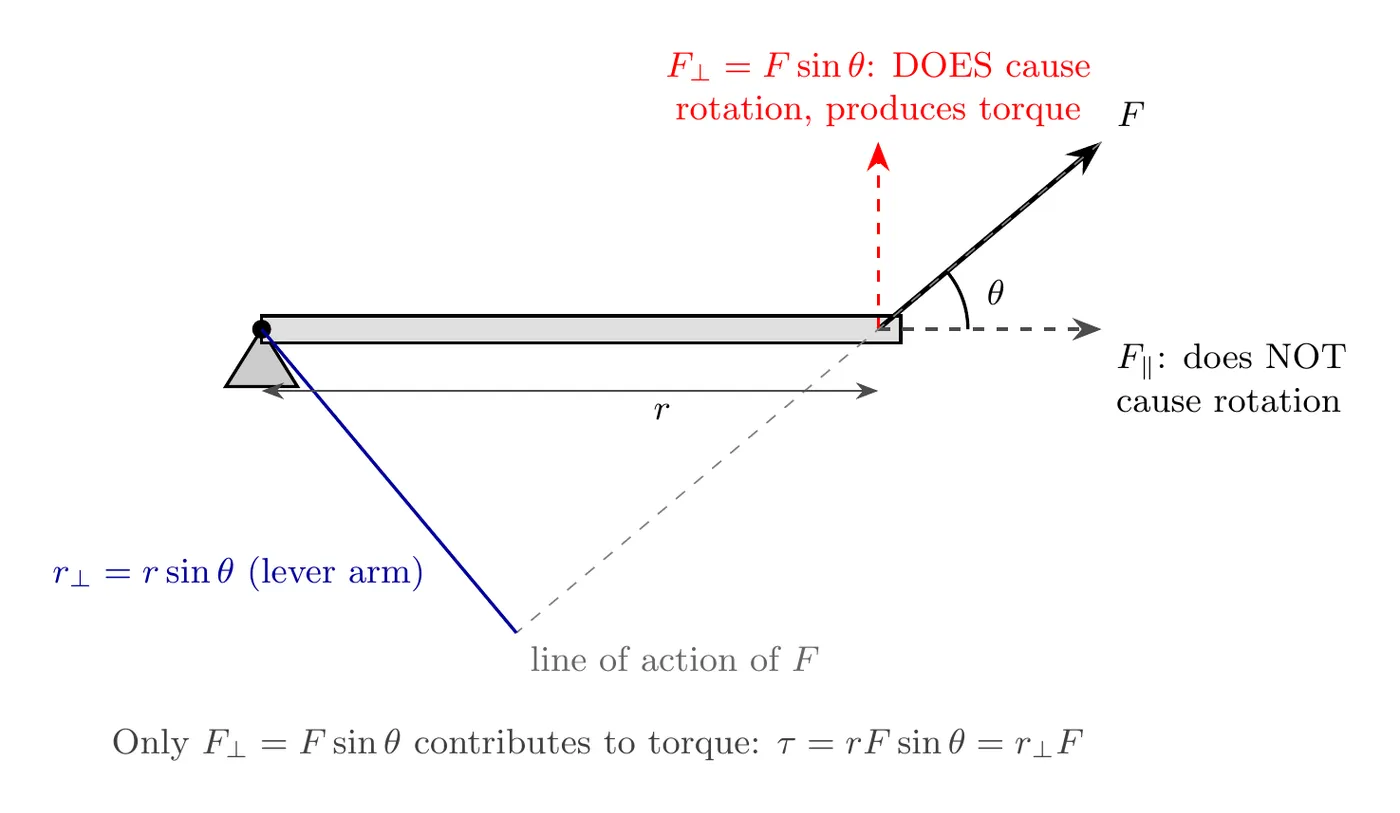
The lever arm ( sin θ, using the r and θ from the formula below) is the perpendicular distance from the axis of rotation to the line of action of the force. That word “perpendicular” is key, the lever arm isn’t necessarily the distance from the pivot to where the force is applied, it’s the perpendicular distance from the pivot to the force’s actual line of action.
Opening a door example: push perpendicular to the door at the knob, and the lever arm is the full distance from hinge to knob, making it easy to open (large torque). Push parallel to the door (toward or away from the hinge), and the perpendicular component is zero, making it impossible to open (zero torque). Push near the hinge instead, and the lever arm shrinks, making it hard to open (small torque). This is exactly why doorknobs sit far from the hinges, and why you naturally push perpendicular to the door.
The Torque Formula
where is torque, is the distance from the axis to the point where the force is applied (in meters), is the applied force’s magnitude in Newtons, and is the angle between the force vector and the radius (the line from the axis to that point). The lever arm is the perpendicular part of that distance, r sin θ. Units are Newton-meters (N·m).
Torque and energy share the unit N·m (equivalent to Joules), but torque isn’t energy, and we deliberately write it as N·m rather than J to keep that distinction clear.
Maximum torque happens at , when force is perpendicular to the radius: , so , the most effective way to create rotation.
Zero torque happens at or , when force is parallel or antiparallel to the radius: , so , no rotation results no matter how big the force is.
In the general case, only the perpendicular component contributes: .
Direction of Torque
Torque is technically a vector pointing along the rotation axis, but in AP Physics 1 we usually work in 2D, where torque is either positive (causing counterclockwise rotation, associated with “opens/loosens,” lefty-loosey) or negative (causing clockwise rotation, associated with “closes/tightens,” righty-tighty).
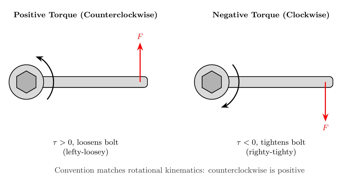
AP Physics 1 only asks for the size of a torque and whether it tends to turn the system clockwise or counterclockwise about the axis. Treating torque as a vector that points into or out of the page (the right-hand rule) is beyond the course. A handy memory aid for the signs: lefty-loosey means counterclockwise loosens bolts (positive torque), and righty-tighty means clockwise tightens bolts (negative torque).
Torque Diagrams
Torque diagrams look similar to free body diagrams, but they show forces at their actual points of application rather than all bunched at the center.
To build one: draw the rigid object (beam, rod, lever, whatever it is), mark the pivot point or rotation axis, draw each force at its actual point of application (with vector, magnitude, direction, and distance from the pivot labeled), and identify each lever arm (the perpendicular distance).
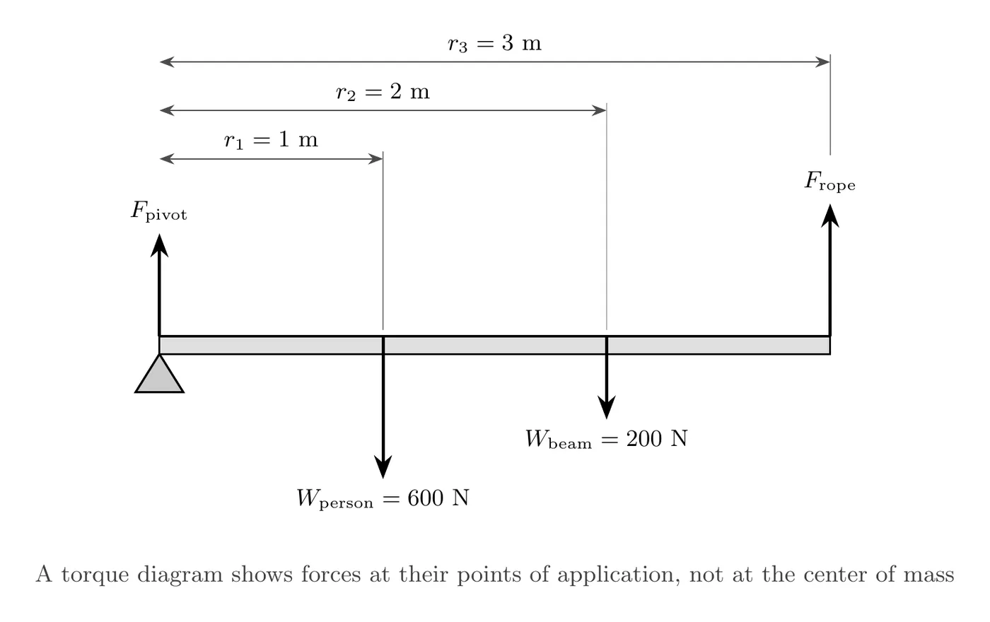
The key difference from a free body diagram: a free body diagram draws all forces from the center of the object, while a torque diagram draws forces exactly where they’re actually applied.
On the AP exam this is called a force diagram. Like a free body diagram, it shows each force’s direction and relative size (a force twice as big gets an arrow about twice as long), and it also shows where each force acts relative to the axis of rotation. Many problems use both: a free body diagram for the forces (linear motion) and a force diagram for the torques (rotation).
Rotational Equilibrium
For a rigid object in rotational equilibrium, either not rotating or rotating at constant :
This means the counterclockwise torques balance the clockwise torques, or equivalently, with appropriate signs for direction.
This is the rotational version of Newton’s First Law: if net torque is zero, angular velocity is constant, . That covers static equilibrium (, not rotating) and dynamic equilibrium (, rotating steadily). Real-world examples include a balanced seesaw (not moving), a ceiling fan at constant speed, and a spinning figure skater before pulling their arms in.
Worked Example: Beam in Equilibrium
A rigid, 2-meter beam lies horizontally, free to pivot at one end. Two forces keep it at rest: a 10 N force applied 1 meter from the pivot at 37° above horizontal, and an unknown force applied 2 meters from the pivot, straight down (perpendicular to the beam). Find .
Identifying torques: the pivot is at the left end. The 10 N force acts at m with a perpendicular component pointing upward, creating counterclockwise (positive) torque. The force acts at m, pointing straight down, creating clockwise (negative) torque.
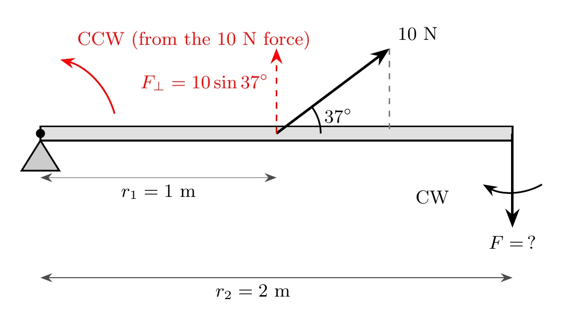
Applying equilibrium: for the beam to stay at rest, , or in terms of magnitudes, .
Calculating :
The 10 N force creates about 6.0 N·m of counterclockwise torque. We use because that’s the component of the 10 N force actually perpendicular to the beam.
Solving for : since is perpendicular to the beam, and , giving . Setting the magnitudes equal:
A downward force of roughly 3 N at the end of the beam balances the torque from the angled 10 N force, keeping everything in rotational equilibrium.
Why is smaller than 10 N? Two reasons: a lever arm advantage, since acts at 2 m from the pivot (farther than the 10 N force’s 1 m), meaning less force is needed for the same torque; and a perpendicular advantage, since acts fully perpendicular () while only part of the 10 N force is perpendicular (). Combined, ends up much smaller and still balances the system.
Two Equivalent Ways to Calculate Torque
The lever arm is the perpendicular distance from the pivot to the line of action of the force. You can calculate torque either by using the full distance and the angle, , or by first finding the perpendicular distance (the true lever arm) and multiplying by the full force, , where . Both give the same answer, use whichever is easier for a given problem.
Worked Example: Lever Arm of a Bicycle Pedal
A cyclist pushes straight down on a pedal with a 475 N force. The crank arm is 0.175 m long (axle to pedal) and points 50° above the horizontal, toward the front of the bike. Find the torque about the axle both ways.
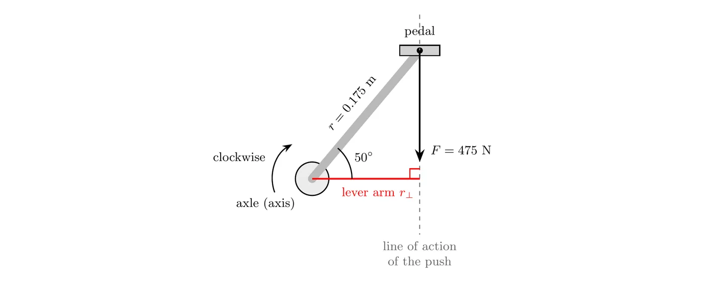
Method 1, lever arm: the push is straight down, so its line of action is a vertical line through the pedal. The lever arm is the perpendicular distance from the axle to that line, which here is the horizontal distance from the axle to the pedal:
We kept a fourth digit in the lever arm so that rounding too early doesn’t change the final answer.
Method 2, : here is the angle between the crank (the line from the axle to the pedal) and the force. The crank points 50° above horizontal and the force points straight down, so :
Both methods agree, since . The push turns the crank clockwise in the picture, so with counterclockwise as positive, N·m. The same push gives the largest torque when the crank is horizontal (lever arm 0.175 m, N·m) and zero torque when the crank points straight up or straight down, because then the line of action passes through the axle.
Real-World Applications
Tools and machines: a longer wrench gives a larger lever arm and more torque, pushing perpendicular to the handle gets the maximum effect, and “cheater bar” extensions work by increasing the lever arm. Doors put doorknobs far from the hinges to maximize , and you naturally push perpendicular to maximize . A wheel and axle system applies force to the wheel (large ) to more easily turn the axle (small ).
Human body: the biceps muscle has a small lever arm, only about 4 cm from the elbow joint, so it needs a large force to lift even a light object, a mechanical disadvantage for force, though an advantage for hand speed. The calf muscle, working through the Achilles tendon, has a very small lever arm too, requiring enormous force just to stand on your toes.
Seesaws and balancing: a heavier person sits closer to the pivot (smaller ), while a lighter person sits farther away (larger ), and balance happens when .
Common Mistakes
Using distance instead of perpendicular distance: if the force isn’t perpendicular, don’t just use the raw distance, either use or find the true perpendicular distance directly.
Forgetting the angle: don’t write when the force is at an angle, it should be with the correct angle included.
Using the wrong angle: don’t measure the angle from vertical if the formula expects the angle from the radius, use the angle between the force vector and the radius (or the complementary angle if needed).
Confusing torque and energy: don’t call torque “work” or measure it in Joules, it’s measured in N·m and represents rotational force, not energy.
Ignoring sign convention: don’t treat every torque as positive, assign signs based on rotation direction, counterclockwise positive, clockwise negative.