

5.6 - Newton’s Second Law in Rotational Form
From Equilibrium to Acceleration
Following the progression of Newton’s Laws for rotation: the First Law (previous topic) covers no angular acceleration, . The Second Law (this topic) covers what happens when angular acceleration does occur, changes. The key idea: angular velocity changes whenever a net torque acts on a system.
Newton’s Second Law for Rotation
The rate at which angular velocity changes is directly proportional to the net torque and inversely proportional to the rotational inertia, with the angular acceleration pointing in the same direction as the net torque.
where is net torque in N·m, is rotational inertia in kg·m², and is angular acceleration in rad/s². This is the rotational version of Newton’s Second Law:
Linear Motion | Rotational Motion |
Force causes linear acceleration | Torque causes angular acceleration |
Mass resists linear acceleration | Rotational inertia resists angular acceleration |
On the AP equation sheet, the same law appears solved for the angular acceleration of the system:
Proportionality Relationships
At constant , , directly proportional, double the torque and you double the angular acceleration. For example, pushing harder on a door swings it open with greater angular acceleration.
At constant , , inversely proportional, double the rotational inertia and you halve the angular acceleration. For example, the same push on a heavy door versus a light door: the heavy door (larger ) accelerates more slowly.
Finding Rotational Inertia from a Graph
Since , a graph of angular acceleration versus net torque for one rigid system is a straight line through the origin, and its slope is . That gives a lab method for measuring . Wrap a string around a spool of known radius on the rotating object and pull it with a force sensor, so the applied torque is . Measure the angular acceleration for several different pulls (with a rotary motion sensor, or by timing how long the object takes to turn a known angle from rest and using ). Then plot vs. , draw a best-fit line, and use its slope.
Example: a student collects this sample data for a rotating platform.
Net torque (N·m) | Angular acceleration (rad/s²) |
0.020 | 4.8 |
0.040 | 10.3 |
0.060 | 14.9 |
0.080 | 20.2 |
0.100 | 24.8 |
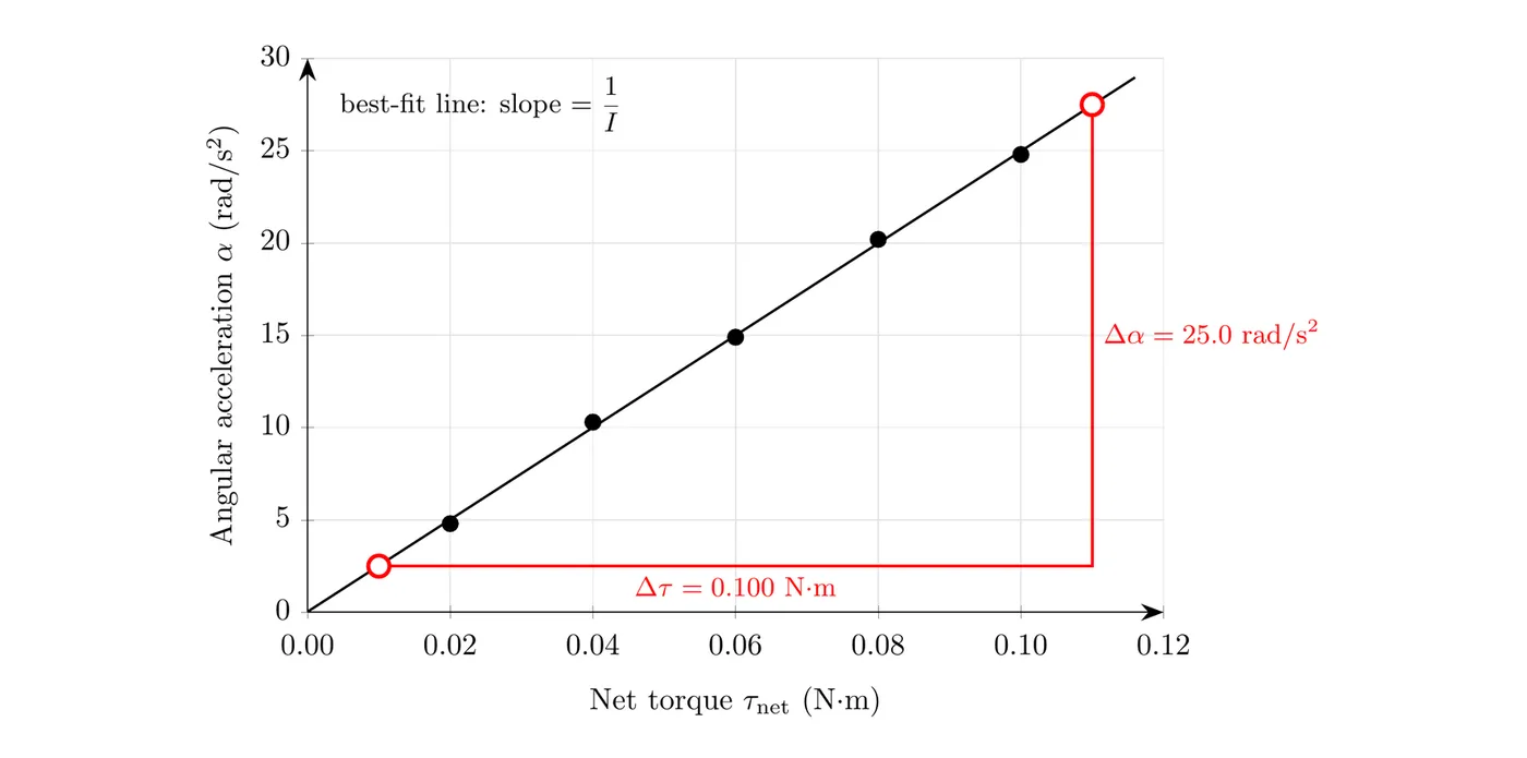
Use two points on the best-fit line, not data points, spread far apart: (0.010 N·m, 2.5 rad/s²) and (0.110 N·m, 27.5 rad/s²).
If the best-fit line crossed the torque axis to the right of the origin instead of going through it, that would point to a small friction torque at the axle: the platform doesn’t speed up until the applied torque beats friction. The slope would still give .
Plotting vs. works well because the relationship is linear. If you instead kept the torque fixed and changed , a graph of vs. would curve (inverse relationship). To get a straight line from that kind of data, plot vs. , which has slope .
Analyzing Rotating Systems
For systems combining both translation and rotation, you typically need separate analyses. Draw a rigid body diagram showing all forces at their points of application, and identify the axis of rotation. Write separate equations: and for linear motion, for rotational motion. Then connect them with , linking the translational acceleration at the edge to the angular acceleration.
Connecting Linear and Angular Acceleration
where is tangential (linear) acceleration in m/s², is radius in meters, and is angular acceleration in rad/s². Use this whenever rotational and linear motion are coupled, pulleys with hanging masses, rolling wheels, and similar setups.
Example: Pulley System Analysis
For a pulley with masses hanging on either side, the forces at the axis (weight, support) contribute zero torque since there, while tension forces at the rim create the torques that cause rotation. Tensions on opposite sides create opposite torques, one rotating counterclockwise (positive), the other clockwise (negative), and the net torque is the difference between them.
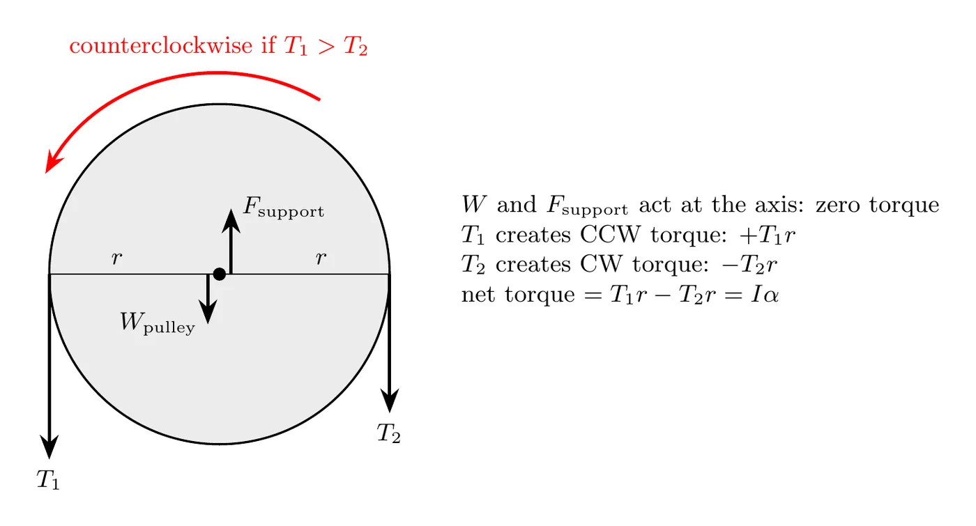
For the hanging blocks, build separate free body diagrams, apply , and link the tensions between the pulley and block equations.
Worked Example: Modified Atwood Machine with Pulley Mass
A disk-shaped pulley (mass 1.2 kg, radius 0.15 m) has a person pulling downward on the left rope with a steady 28 N force, while a 0.7 kg block hangs on the right side. The pulley rotates frictionlessly. Use m/s². Find the tension on the right side.
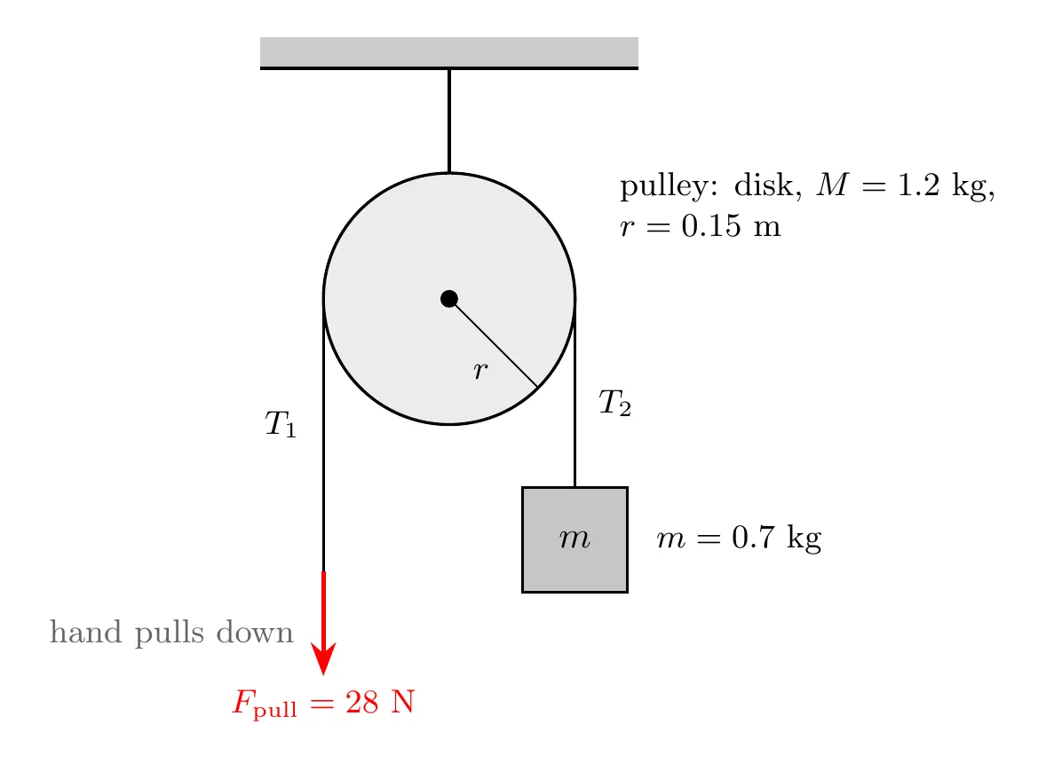
Left side (the person’s pull): the rope is treated as massless, so the net force on its end is zero even while the system accelerates: N.
Right side (the block): forces are tension (up) and weight (down). With up as positive:
We need before we can find .
The pulley (rotation): for a disk, . Torques about the center: creates counterclockwise torque (), creates clockwise torque ().
Linking to linear acceleration with :
Substituting :
Dividing by :
Solving the system: we have and . Substituting :
Substituting into :
Multiplying through by 0.6:
The tension in the right rope is approximately 18 N. As a sanity check, the block’s weight is N, and N exceeds that, which makes sense since the block is accelerating upward, being pulled up by the rotating pulley.
Problem-Solving Strategy Summary
For combined rotation-translation problems: draw separate diagrams (a rigid body diagram for the rotating object, free body diagrams for translating objects), write for translating objects and for rotating ones, connect them with , and solve the resulting system, often through substitution and strategic elimination of variables.
Worked Example: Linear and Rotational Analyses Done Separately
Sometimes the linear and rotational parts of a problem aren’t tied together by , so each analysis has to be done on its own. A uniform 2.0 kg disk of radius 0.25 m lies flat on frictionless ice, with about its center. A string wrapped around its rim is pulled horizontally with a constant 6.0 N force. Find the acceleration of the disk’s center of mass and its angular acceleration.
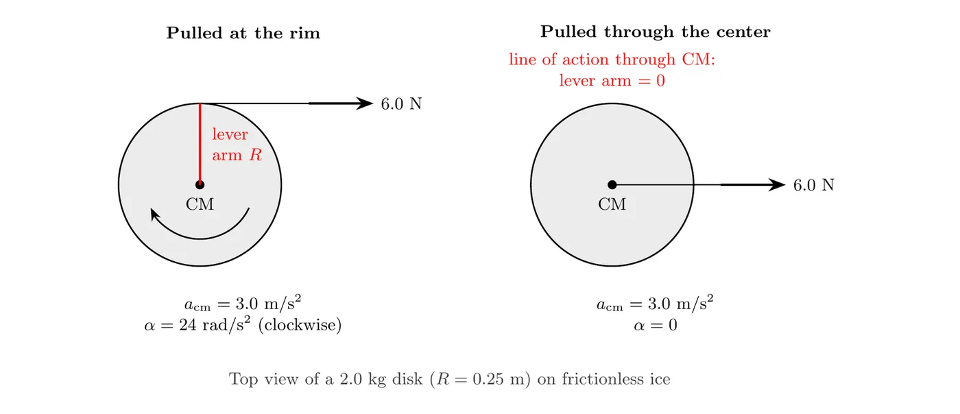
Linear analysis (the disk as an object): the only horizontal force is the 6.0 N pull. Gravity and the normal force cancel vertically, and the ice exerts no friction. Newton’s second law for the center of mass doesn’t care where on the disk the force acts:
Rotational analysis (the disk as a rigid system): the string pulls along a line tangent to the rim, so the lever arm about the center is the full radius . Keep the extra digits in for the next step:
Compare: pull with the same 6.0 N through the center (say, with the string tied to a pin at the center) and the center of mass still accelerates at 3.0 m/s², but the lever arm is zero, so the disk doesn’t spin. Moving the force to the rim adds rotation without taking anything away from the linear motion. Also notice that m/s² is not equal to m/s². Nothing ties the spinning to the sliding here (the disk isn’t rolling on anything), which is why the two analyses have to be done separately.
Real-World Applications
Yo-yos: the string unwinds from a small-radius axle, creating a torque that drives both rotation and translation. A larger axle radius is easier to accelerate, and the mass distribution () affects how long the yo-yo “sleeps” at the bottom.
Wheels and axles: applying force at a large radius (the wheel) produces a large torque on a small radius (the axle), the principle behind steering wheels, winches, and gears.
Flywheels: a large resists angular acceleration, which smooths out engine rotation and stores rotational kinetic energy.
Rolling motion: an object rotating and translating at once, with the no-slip condition and tying the two together, and both rotational and translational kinetic energy need to be considered.
Common Mistakes
Forgetting to use the correct : don’t use for a disk, use the shape-specific formula, .
Wrong sign on torques: don’t give both tensions positive torque, opposite sides of a pulley create opposite torques, one positive, one negative.
Confusing and : don’t set directly, it’s , always including the radius.
Including axis forces in torque: don’t include weight or support forces acting right at the axis in the torque equation, they contribute zero torque since .
Not connecting the systems: don’t treat the pulley and hanging masses as fully independent, the tensions link them together, and their accelerations relate through .