

5.5 - Rotational Equilibrium and Newton’s First Law in Rotational Form
Newton’s Laws Extended to Rotation
Newton’s Laws govern rotational motion too, with the right substitutions. Newton’s First Law for rotation deals with equilibrium, when objects don’t rotate, or rotate at a constant angular velocity.
Recall the linear version: if net force is zero, velocity stays constant (including zero), describing inertia and equilibrium. The rotational version: if net torque is zero, angular velocity stays constant (including zero), describing rotational inertia and rotational equilibrium.
The rotational first law works in both directions. A system has a constant angular velocity only if the net torque on it is zero. So if the torques on a rigid system are not balanced, its angular velocity must be changing: it speeds up, slows down, or starts or stops spinning. That’s the rotational corollary to Newton’s second law, and 5.6 turns it into an equation.
Two Types of Equilibrium
Translational (linear) equilibrium happens when the net force on an object is zero, . The object doesn’t accelerate linearly, either at rest () or moving at constant velocity (, ).
Rotational equilibrium happens when the net torque on an object is zero, . The object doesn’t accelerate rotationally, either not rotating () or rotating at constant angular velocity (, ).
An object can be in rotational equilibrium without being in translational equilibrium, and vice versa, because net force and net torque are separate conditions. Check each one on its own.
Rotational equilibrium without translational equilibrium: drop a meter stick so it falls flat without spinning. Gravity is the only force, so the net force isn’t zero and the stick speeds up as it falls. But gravity acts at the center of mass, so it exerts no torque about the center of mass, and the stick keeps the same angular velocity (zero) all the way down.
Translational equilibrium without rotational equilibrium: turn a steering wheel by pushing up on the left side and down on the right side with equal-sized forces. The two forces add to zero, so the wheel’s center doesn’t accelerate, but both forces twist the wheel clockwise, so the net torque isn’t zero and the wheel’s angular velocity changes.
Static Equilibrium: Both Conditions Required
Static equilibrium means an object is completely at rest, neither translating nor rotating. Both conditions must hold simultaneously:
No net force means no linear acceleration, and no net torque means no angular acceleration.
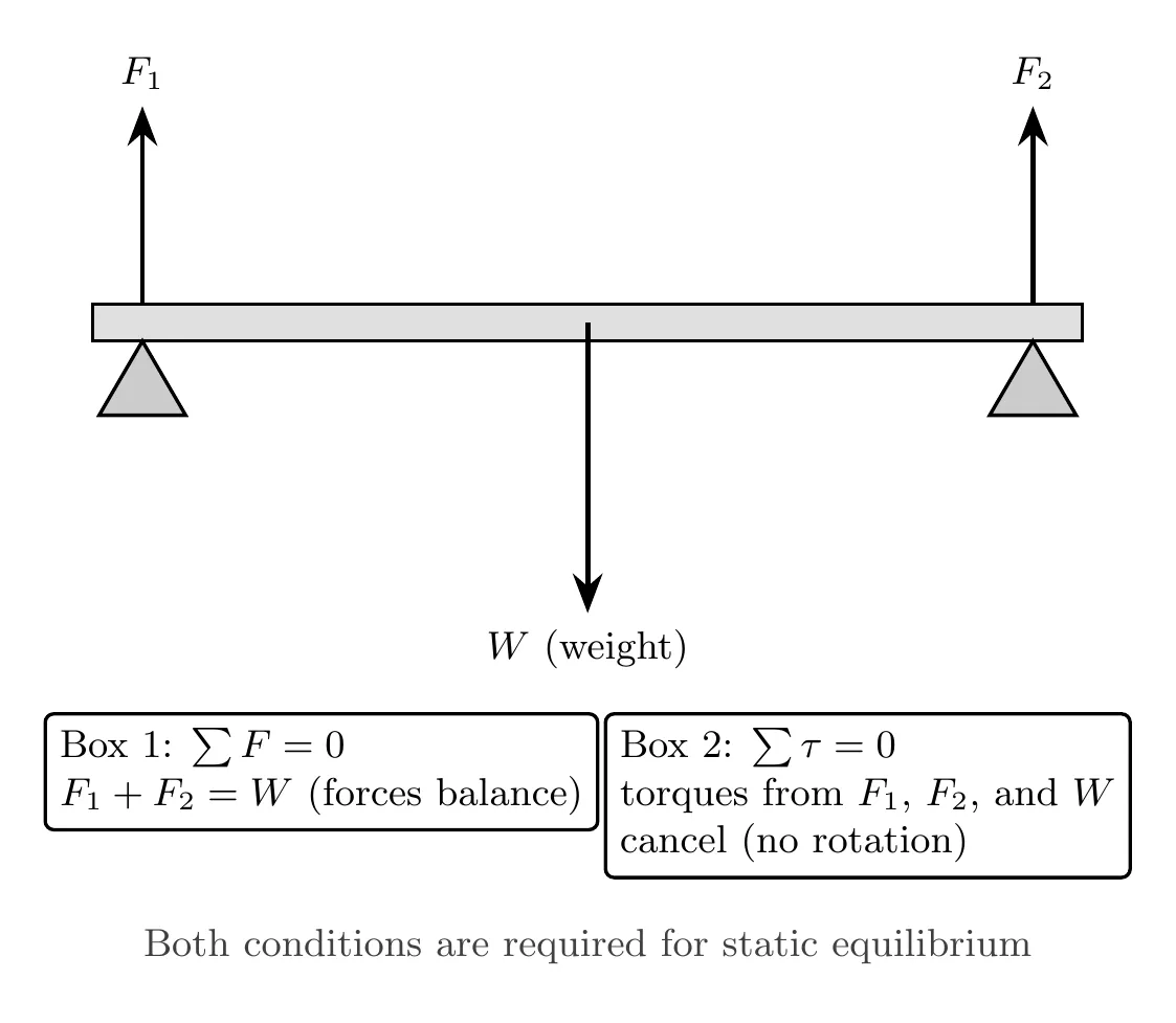
Examples of static equilibrium include a bridge at rest supporting cars, a balanced seesaw with children sitting still, and a ladder leaning against a wall without moving. Things that are not in static equilibrium include a spinning wheel at constant speed (rotating, though in rotational equilibrium) and a car driving at constant velocity (moving, though in translational equilibrium).
Force Diagrams for Rotational Problems
For rotational equilibrium problems, we build rigid body diagrams (RBDs) or force diagrams, similar to free body diagrams, except forces are shown at their actual points of application rather than all bunched at the center. This matters because torque depends on where a force is applied, not just its magnitude and direction.
To create one: draw the extended object (beam, ladder, door), mark the axis of rotation or pivot point, draw each force vector where it actually acts (contact forces where surfaces touch, weight at the center of mass, tension where a rope or cable attaches), label forces and their distances from the axis, and note any angles for forces that aren’t perpendicular to their lever arms.
Writing Equilibrium Equations
Static equilibrium problems in 2D need three equations:
These three equations let you solve for up to three unknowns.
Draw-Sum-Solve: draw the force diagram (rigid body diagram) showing all forces at their points of application, mark distances and angles, and choose an axis of rotation. Sum by writing , , and . Solve using algebra, sometimes solving one equation first and substituting into another.
Strategic Choice of Axis of Rotation
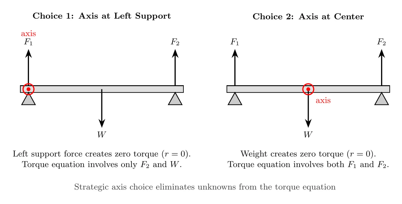
A powerful trick: choose the axis of rotation right at a point where an unknown force acts. Since torque is , if (the force acts right at the axis), that force contributes zero torque and drops out of the torque equation entirely, leaving fewer unknowns to solve for.
For example, with a beam supported at two points with unknown forces at both, choosing the axis at one support eliminates that support’s force from the torque equation (), letting you solve for the other support force first, then use the force equations to find the first. You can choose any axis, the physics doesn’t change, but a strategic choice simplifies the algebra a lot.
Sign Convention for Torques
Counterclockwise torques are positive, clockwise torques are negative. Alternatively, you can just set counterclockwise torque magnitudes equal to clockwise torque magnitudes, . Both methods work, use whichever feels more natural.
Worked Example: Painter on a Plank
A uniform 25.0 kg plank, 4.00 m long, rests on two supports: support A at the left end and support B 1.00 m from the right end (3.00 m from A). A 65.0 kg painter stands on the plank 1.00 m from the left end. Use m/s². Find the force each support exerts on the plank, then find how far past support B the painter can walk before the plank starts to tip.
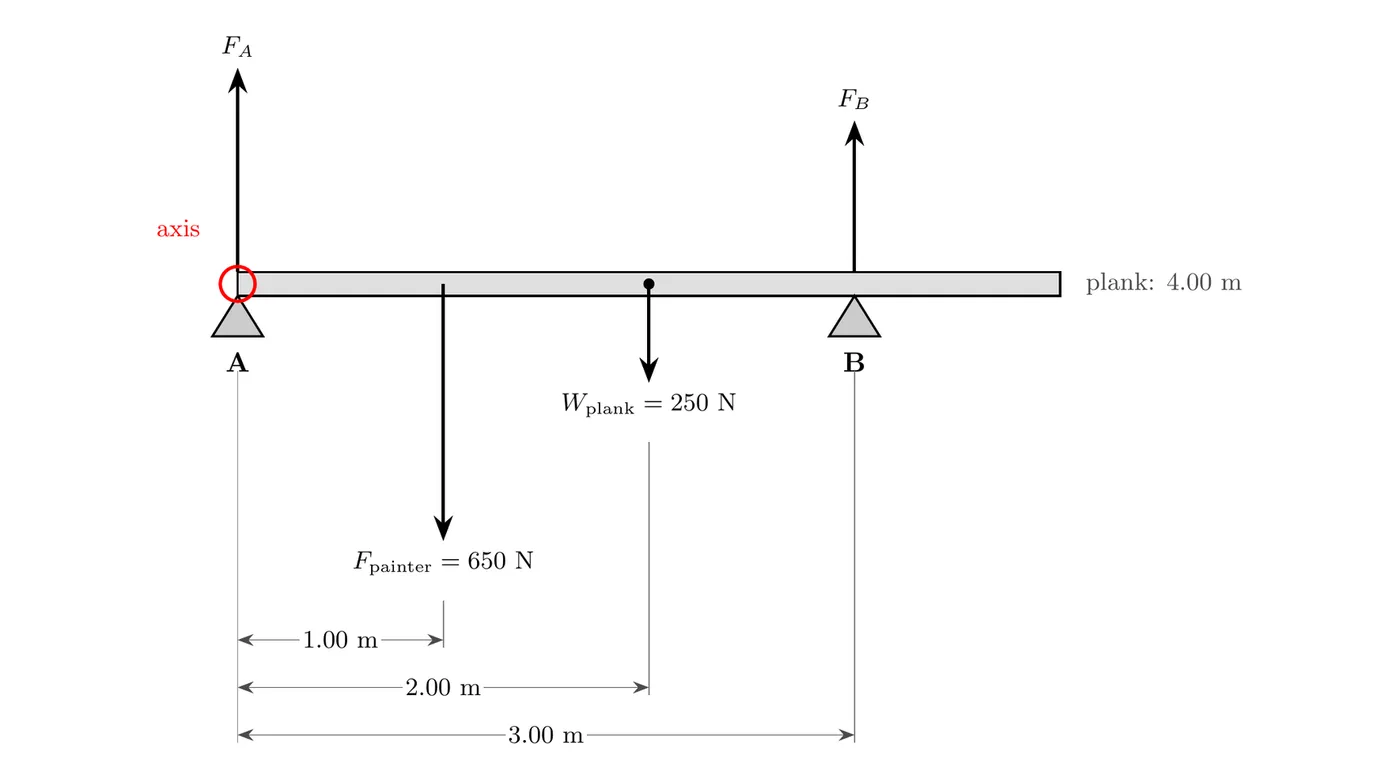
Draw: four vertical forces act on the plank. The plank’s weight, N, acts at its center, 2.00 m from A. The painter’s feet push down on the plank with a force equal to the painter’s weight, N, 1.00 m from A. The supports push up with and . The arrows are drawn to scale, so bigger forces get longer arrows. Put the axis at A, so has no lever arm and drops out of the torque equation.
Sum the torques about A: every force is perpendicular to the plank, so each lever arm is just the distance from A. turns the plank counterclockwise (positive), and both downward forces turn it clockwise (negative):
Sum the forces to find the other support:
Check with a different axis: about B, acts 3.00 m to the left and turns the plank clockwise, while the plank’s weight (1.00 m left of B) and the painter (2.00 m left of B) both turn it counterclockwise. So , which gives N again. Any axis works. A smart axis just saves algebra.
How far past B can the painter go? As the painter walks right past B, their push turns the plank clockwise about B, while the plank’s own weight (1.00 m to the left of B) turns it counterclockwise. gets smaller as the painter moves right, and the plank is about to tip when reaches zero. Set and balance the torques about B, with the painter a distance past B:
The painter can only walk 0.385 m past support B, so the last 0.615 m of the plank is off limits. The answer doesn’t depend on : both forces are a mass times , so gives the same 0.385 m.
Worked Example: Ladder Against a Wall
A uniform 16 kg ladder, 4.8 m long, leans against a frictionless wall at 65° from the ground. The ground has friction. Find the minimum friction force at the ground needed to keep the ladder from sliding.
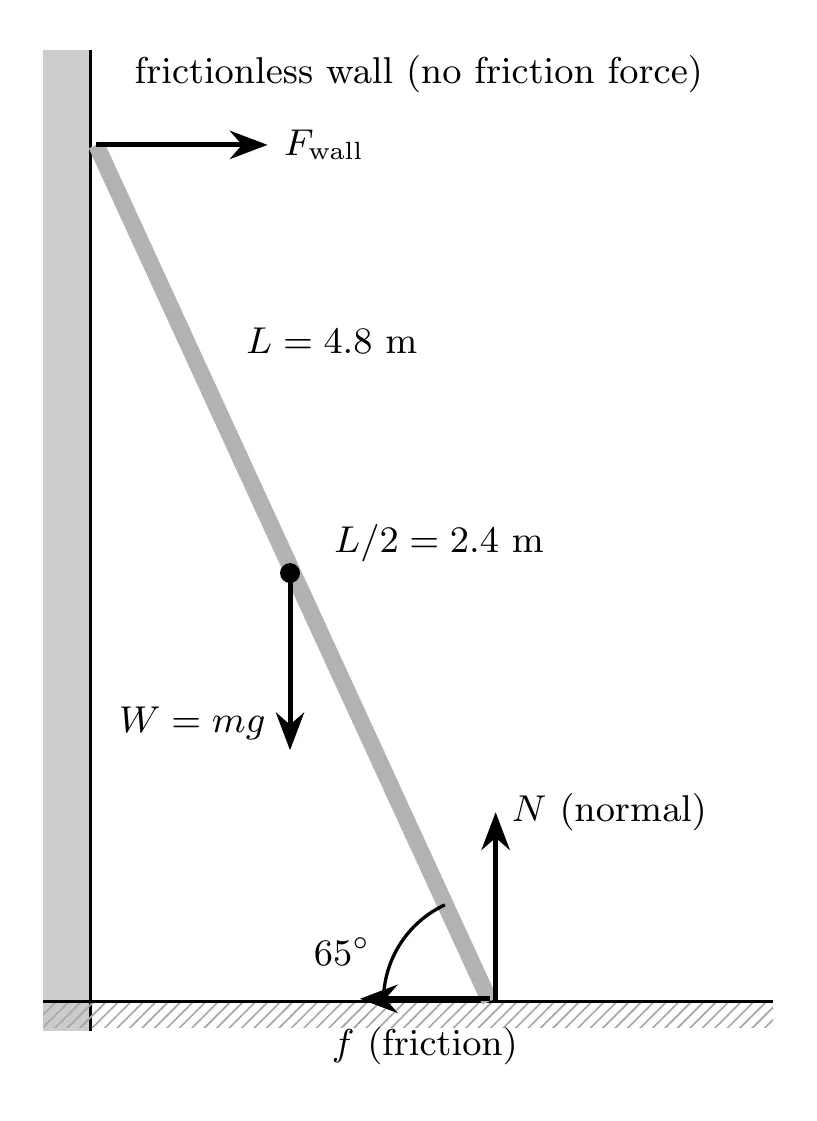
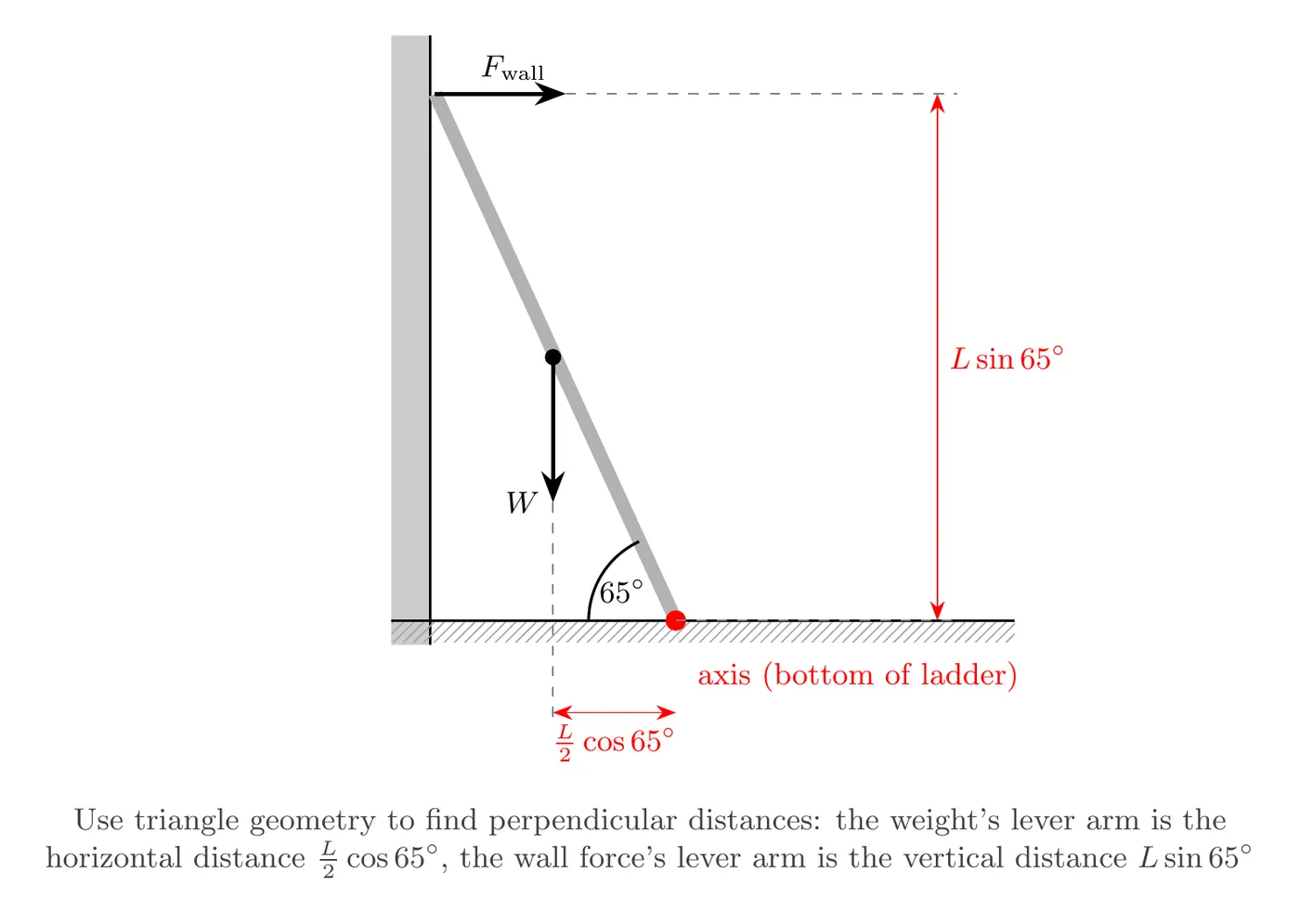
Draw: the forces on the ladder are weight (, acting downward at the center of mass, the middle of the uniform ladder), normal force from the ground (, acting upward at the bottom), friction from the ground (, acting horizontally at the bottom, opposing the tendency to slide), and normal force from the wall (, acting horizontally at the top, since the wall is frictionless and can only push perpendicular). The axis is placed at the bottom of the ladder, which eliminates both and from the torque equation since they both act right at that axis, .
Sum: horizontal forces give , a relationship we’ll use later. Vertical forces give N.
For torques about the bottom of the ladder: the weight acts at the center ( from the bottom), so its perpendicular distance (the horizontal distance) is L/2 times the cosine of ; acts at the top ( from the bottom), so its perpendicular distance (the height) is L times the sine of ; and and both act at the axis, contributing zero torque. Setting counterclockwise equal to clockwise:
Solve: and appear on the left side, so dividing both sides by L sin(65°) leaves:
From the horizontal equilibrium relationship, N. The minimum friction force required is about 37 N.
Finding the coefficient of friction (an extension): if asked, . The ground needs a coefficient of static friction of at least about 0.23 to keep the ladder from sliding.
Understanding Perpendicular Distances
Why did we use trig like in the ladder problem? Because we need the actual perpendicular distance from the axis to each force’s line of action, which requires a bit of geometry. For the weight, acting straight down at the ladder’s center, the perpendicular distance from the bottom (axis) is the horizontal distance . For the wall force, acting horizontally at the top, the perpendicular distance from the bottom is the height . The general principle: use geometry, often sine or cosine of the given angle, to find the true perpendicular distance between the axis and each force’s line of action.
Making the Problem Harder
Instructors can raise the difficulty by adding a person on the ladder (their weight adds torque, and their position along the ladder changes the lever arm, raising the question of how high they can climb before it slips), using different angles (steeper angles change the force requirements and relate the angle to a minimum friction coefficient), adding friction to both surfaces (more unknowns, more equations), asking “how high” questions (finding the critical position where slipping starts), or using a non-uniform ladder (where the center of mass isn’t at the geometric center, requiring the actual mass distribution).
Common Mistakes
Drawing forces at the wrong location: don’t draw all forces from the center like a free body diagram, draw them where they actually act for torque calculations.
Forgetting a force: don’t omit the wall force or friction just because they weren’t explicitly named, identify every contact point and its associated force.
Using the wrong distance: don’t use the total length when you should use the distance to the center of mass, for uniform objects, weight acts at the geometric center ( for a rod or ladder).
Confusing perpendicular distance: don’t use the full length as the lever arm if the force isn’t perpendicular, calculate the true perpendicular distance using geometry (often trig).
Not checking both conditions: don’t check only while ignoring , static equilibrium needs both force balance and torque balance.
Poor axis choice: it’s not wrong, but it’s inefficient, to choose an axis where no unknowns act. A better strategy is choosing an axis where an unknown force acts, to eliminate it from the torque equation.