

4.2 - Simple Circuits
What a Circuit Is
An electric circuit is a closed loop pathway that charge can flow around. Circuits let you actually put electrical energy to work by giving the current a controlled path to follow.
Essential Components
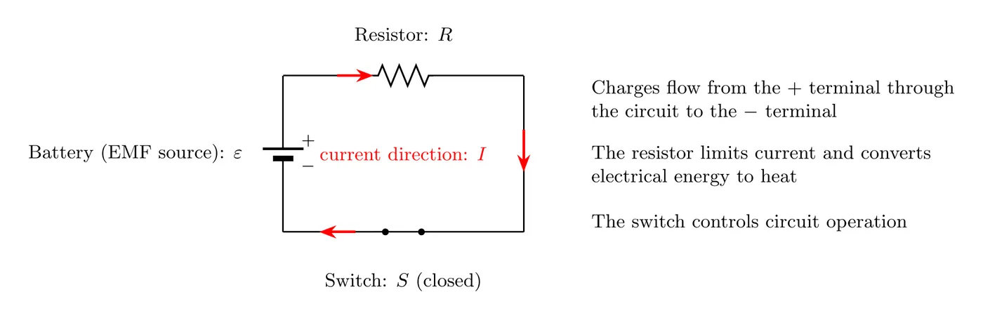
Conducting wire provides the pathway for charge. It’s made of conductive material (usually copper), connects all the circuit elements, and forms the closed loops.
Power source (EMF source) supplies the voltage that drives the charge. Common ones are batteries (chemical energy to electrical), generators (mechanical to electrical), and power supplies (converting AC to DC or providing a regulated voltage). Its job is to create the potential difference that gets the electrons moving.
Load elements are what actually use the energy. Resistors turn electrical energy into heat and limit current, light bulbs turn it into light and heat, capacitors store energy in an electric field, and inductors store energy in a magnetic field (covered later). These are the things that consume or store what the source provides.
Switch controls whether the circuit is on or off. An open switch breaks the circuit and stops the current, and a closed switch completes the circuit and lets current flow.
Measuring Instruments (Optional)
An ammeter measures current (in amperes) and must be wired in series with whatever element you’re measuring the current through. Ideally it has zero resistance, so it doesn’t disturb the circuit.
A voltmeter measures potential difference (in volts) and must be wired in parallel across whatever element you’re measuring. Ideally it has infinite resistance, so it draws no current from the circuit.
Types of Circuits
Closed Circuit
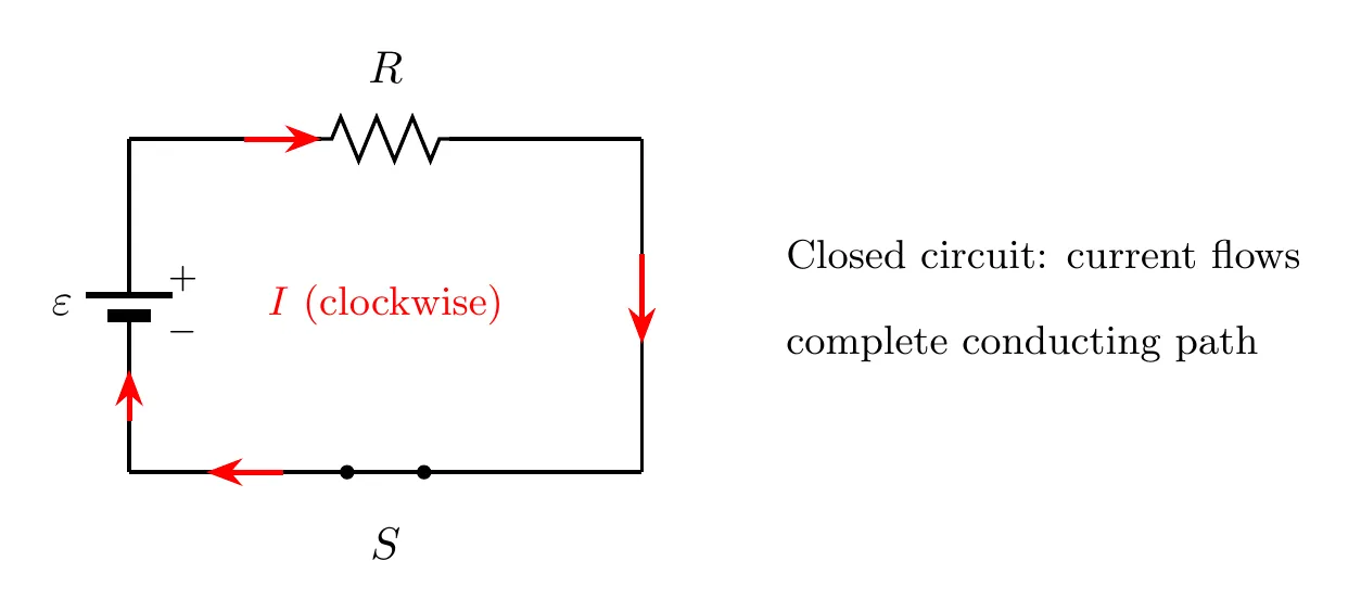
A closed circuit has a complete, unbroken path for charge to flow. The switch is closed, current flows continuously around the loop, energy moves from the source to the load, and this is the normal operating condition.
Open Circuit
An open circuit has a break somewhere in the path, so charge can’t flow. The switch is open (or there’s a break in the wire), no current flows, a potential difference exists across the break, and no energy reaches the loads.
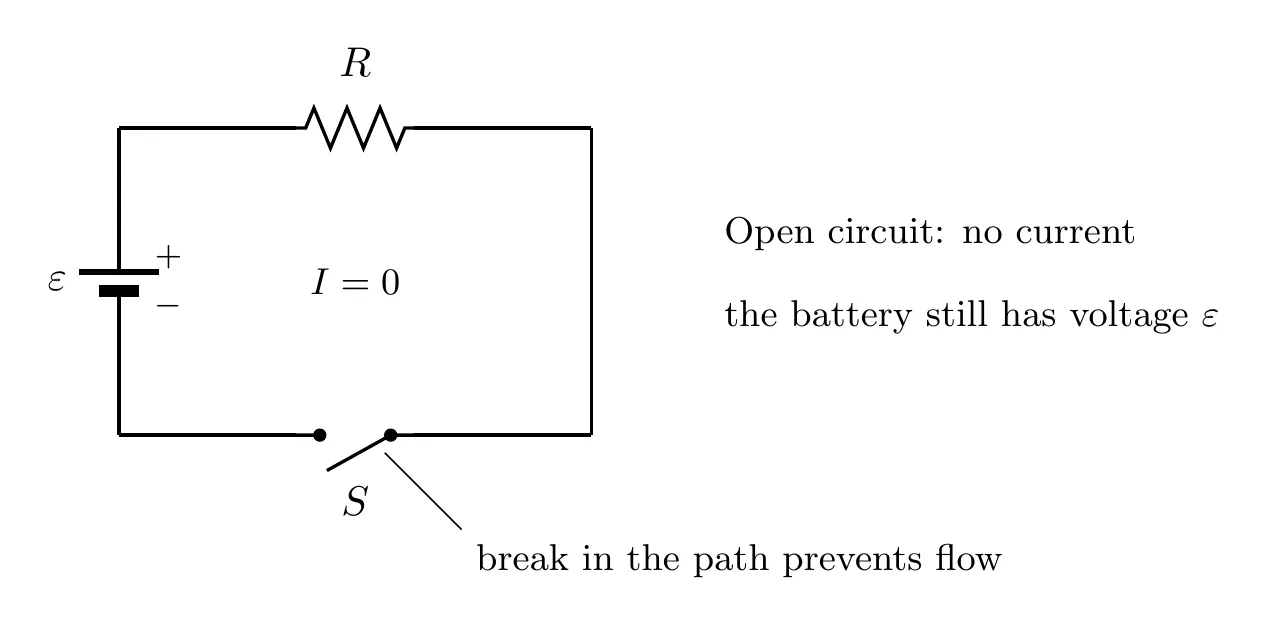
Common causes: an intentionally opened switch, a broken wire, a blown fuse, or a disconnected component.
Short Circuit
A short circuit is when charge finds a path with essentially no resistance, bypassing the load it was supposed to go through. You get very high current (which can be dangerous), almost no potential difference across the short, load elements that get bypassed and stop working, and a real risk of damaged components or fire.
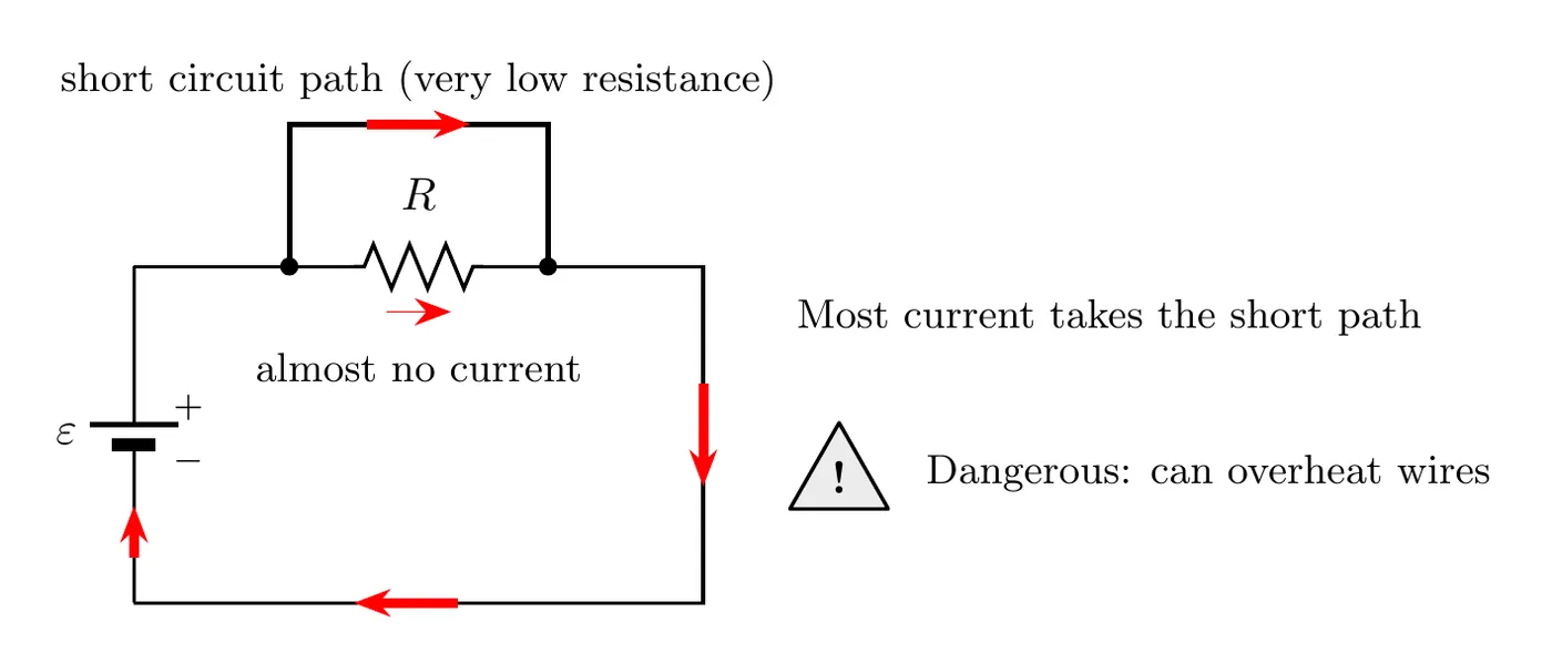
Why shorts are dangerous. The current blows up, since and if then shoots toward infinity. The wires overheat because of the dissipated in the wire’s own resistance. Shorts trip circuit breakers (which is the safety mechanism doing its job), and if the protection fails, they can start fires.
That’s exactly why circuit breakers exist in your house: they automatically open the circuit when the current gets too big, keeping the wires from overheating and catching fire.
What makes it a short, exactly. A short circuit is a path where charge can flow with no change in potential. An ideal wire has zero resistance, so along it no matter how much current it carries. Anything connected across the two ends of that wire has the same potential on both sides, so it has and gets no current.
Example: A 12 V battery drives a 4.0 Ω resistor and an 8.0 Ω resistor in series. The current is A, so the 8.0 Ω resistor has 8.0 V across it. Now connect a wire across the 8.0 Ω resistor. The wire forces between the resistor’s two ends, so the 8.0 Ω resistor gets no current at all. Every bit of current takes the wire, and the battery now sees only 4.0 Ω: A, three times what it was.
Circuit Schematics
A circuit schematic (or circuit diagram) is a standardized picture of a circuit built from symbols. Schematics give you a clean, simple view of how things connect, they use symbols everyone recognizes, they show the electrical relationships without worrying about physical layout, and they let you analyze a circuit without building it.
Important: where things sit in the schematic has nothing to do with where they sit in real life. The schematic shows electrical connections, not physical positions.
What does matter is how the elements are connected. The same parts wired differently make a different circuit. Example: two identical 6.0 Ω bulbs and a 12 V battery. In series, the current is A and each bulb has 6.0 V across it. In parallel, each bulb gets the full 12 V and carries A, so each one uses four times the power (24 W instead of 6.0 W) and glows much brighter.
Standard Circuit Symbols
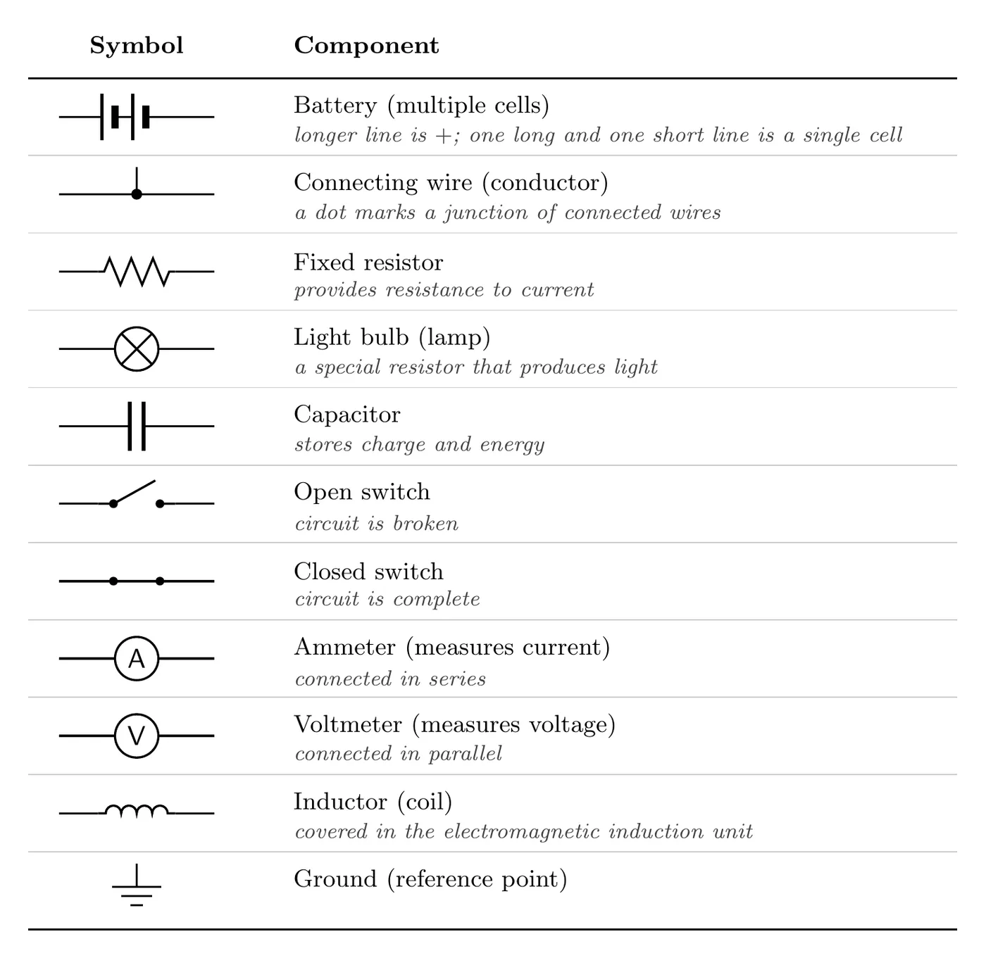
A few details worth pinning down. On a battery, the long line is the positive terminal and the short line is the negative one, and multiple pairs mean multiple cells (higher voltage). On a switch, an angled line means open (gap in the circuit, no current) and a straight connecting line means closed (current flows, often just drawn as plain wire). On a resistor, the zigzag stands for resistance to current, though the European standard draws it as a rectangle.
Variable elements. An element you can adjust is drawn with a diagonal arrow through its normal symbol. A resistor with an arrow through it is a variable resistor (a rheostat), like the adjustable resistor in the windshield wiper timer in topic 4.8. A capacitor with an arrow through it is a variable capacitor.
Unless a problem says otherwise, current arrows on AP circuit diagrams show conventional current (the direction positive charge would move), not the electrons.
Reading a Schematic
One Element, Several Loops
A loop is any closed path you can trace through a circuit and end up where you started. Once a circuit has more than one path, a single element can belong to several loops at the same time.
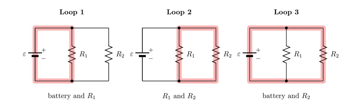
This circuit has three loops. Loop 1 runs through the battery and , loop 2 through and (no battery at all), and loop 3 around the outside through the battery and . So every element here is part of two different loops. That matters for Kirchhoff’s loop rule (topic 4.6/4.7): each loop you trace gives you an equation, and an element shared by two loops shows up in both of them.
Schematic vs. Physical Circuit
A schematic shows the electrical connections and relationships. A physical circuit shows where the components actually sit in space. In a schematic you might draw a battery and resistor side by side in a horizontal line, while in reality the battery is standing vertically, the resistor is stuck in a breadboard, and the wires wander all over. The schematic doesn’t care about any of that. Only the electrical connections matter.
Practical Applications
Household circuit breakers are safety devices that automatically break the circuit when the current climbs past a safe level. In normal operation the breaker is closed and current flows. If a short circuit or overload sends the current way up, the breaker detects it and opens, the circuit becomes open, the current stops, and the wires never get hot enough to start a fire. Once you fix the underlying problem, you can manually close the breaker again to restore power.
Common circuit problems:
Problem | Symptom | Cause | Solution |
Open circuit | Device doesn’t work | Broken wire, open switch, blown fuse | Find and repair the break |
Short circuit | Breaker trips, very high current | Wire touching wire, damaged insulation | Remove the short, replace damaged parts |
High resistance | Dim light, weak performance | Corroded connections, wrong resistor | Clean connections, check components |
Summary of Circuit Requirements
For a working circuit you need a complete conducting path (a closed loop), a voltage source (battery or power supply), a load (resistor, bulb, whatever), and a switch to control it. Optional but handy: an ammeter to measure current and a voltmeter to measure voltage.
Preview
Analyzing circuits quantitatively needs a few more tools: Ohm’s law (linking voltage, current, and resistance), electrical power (the rate of energy transfer), Kirchhoff’s laws (rules for untangling complex circuits), and series versus parallel connections. All of that builds on the basics here.
Common Mistakes
- Confusing open and closed circuits. “Closed” means a complete path with current flowing. “Open” means a broken path with no current. The wording feels backwards at first.
- Drawing the battery symbol wrong. The long line is always positive, the short line is always negative. Flipping them reverses the current direction in your whole analysis.
- Not spotting a short circuit. A wire running straight across a component, bypassing it, is a short. That’s dangerous and sends most of the current around the intended path.
- Thinking schematics show physical layout. They show electrical connections, not physical positions. The real circuit can look totally different in space and still match the schematic.
- Forgetting the switch has to be closed. A circuit with an open switch is an open circuit, no matter how good the power source is. Always check the switch position before deciding whether current flows.