

4.3/4.4 - Resistance, Resistivity, Ohm’s Law, and Electrical Power
Resistance
Resistance is how strongly an object opposes the flow of charge through it.
For a conductor with uniform properties:
where:
- = resistance (Ω, ohms)
- (rho) = resistivity of the material (Ω·m)
- = length of the conductor (m)
- = cross-sectional area (m²)
So , , and .
What that means physically: a longer conductor means more resistance (charges run into more collisions along the way), a bigger cross-section means less resistance (more room for charge to move through), and a higher-resistivity material means more resistance (that’s just a property of the material itself).
For most wires, which are cylindrical, the cross-sectional area is circular: , where is the wire’s radius.
On the AP equation sheet this is , with for the length.
Resistivity belongs to the material. It’s set by the material’s atomic and molecular structure: how many charge carriers are free to move and how often they run into the atoms. It doesn’t depend on the object’s size or shape (resistance does). Copper is about Ω·m, which is why wires are made of it; nichrome, used in heating elements, is about Ω·m; and glass is more than Ω·m.
Resistivity changes with temperature. In a typical conductor, resistivity goes up as the temperature rises: the atoms vibrate harder, so the moving electrons collide with them more often. That’s why a light bulb filament’s resistance climbs as it heats up.
Where the formula comes from. It follows from (topic 4.1). For a uniform wire of length with potential difference across it, the field inside is and the current density is . Substitute:
Example: A heater coil is made from 2.0 m of nichrome wire (resistivity Ω·m) with a diameter of 0.40 mm, so its radius is 0.20 mm:
Factor of change example: you stretch a wire to twice its length. Its volume can’t change, so its cross-sectional area drops to half. Then : the resistance goes up by a factor of 4, not 2.
Non-Uniform Resistivity
When the resistivity changes with position, you have to integrate to get the resistance:
where is the resistivity as a function of position along the conductor. You need this when the resistivity varies with position, when the area changes along the conductor, or when the material isn’t homogeneous. There’s a worked example of this at the end.
Example: A rod is 0.40 m long with a uniform cross-sectional area of m², but its material gets more resistive along its length: , where Ω·m and is measured from one end. The area is constant, so it comes out of the integral:
Sanity check: the resistivity runs from to , so the answer has to land between Ω and Ω. It does.
Ohm’s Law
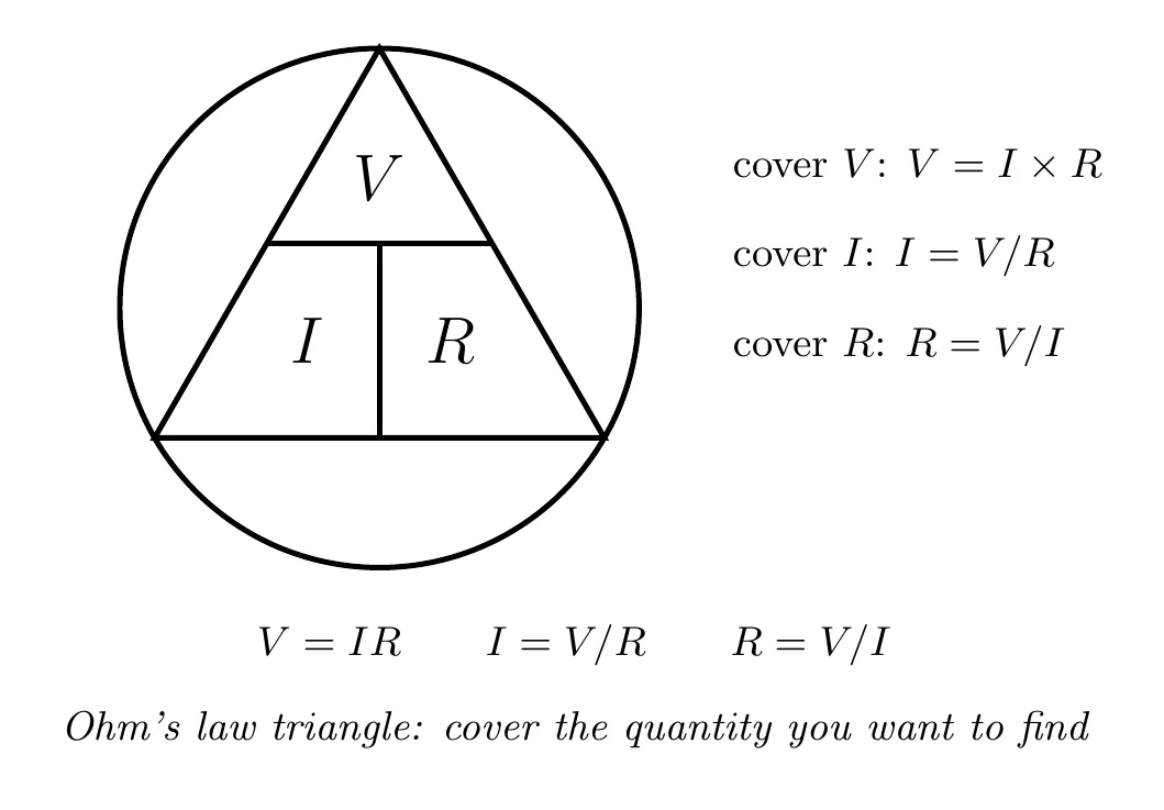
Ohm’s law is the core relationship between voltage, current, and resistance:
where is the potential difference across the element (V), is the current through it (A), and is its resistance (Ω). Rearranged:
In words: the voltage across a resistor is directly proportional to the current through it.
On the AP equation sheet, Ohm’s law is written , with for the potential difference across the element.
Ohmic vs. Non-Ohmic Materials
Ohmic materials hold a constant resistance no matter what voltage or current you apply, so the relationship between and is linear. The test is easy: plot voltage against current, and if you get a straight line, it’s ohmic, with the slope equal to the resistance.
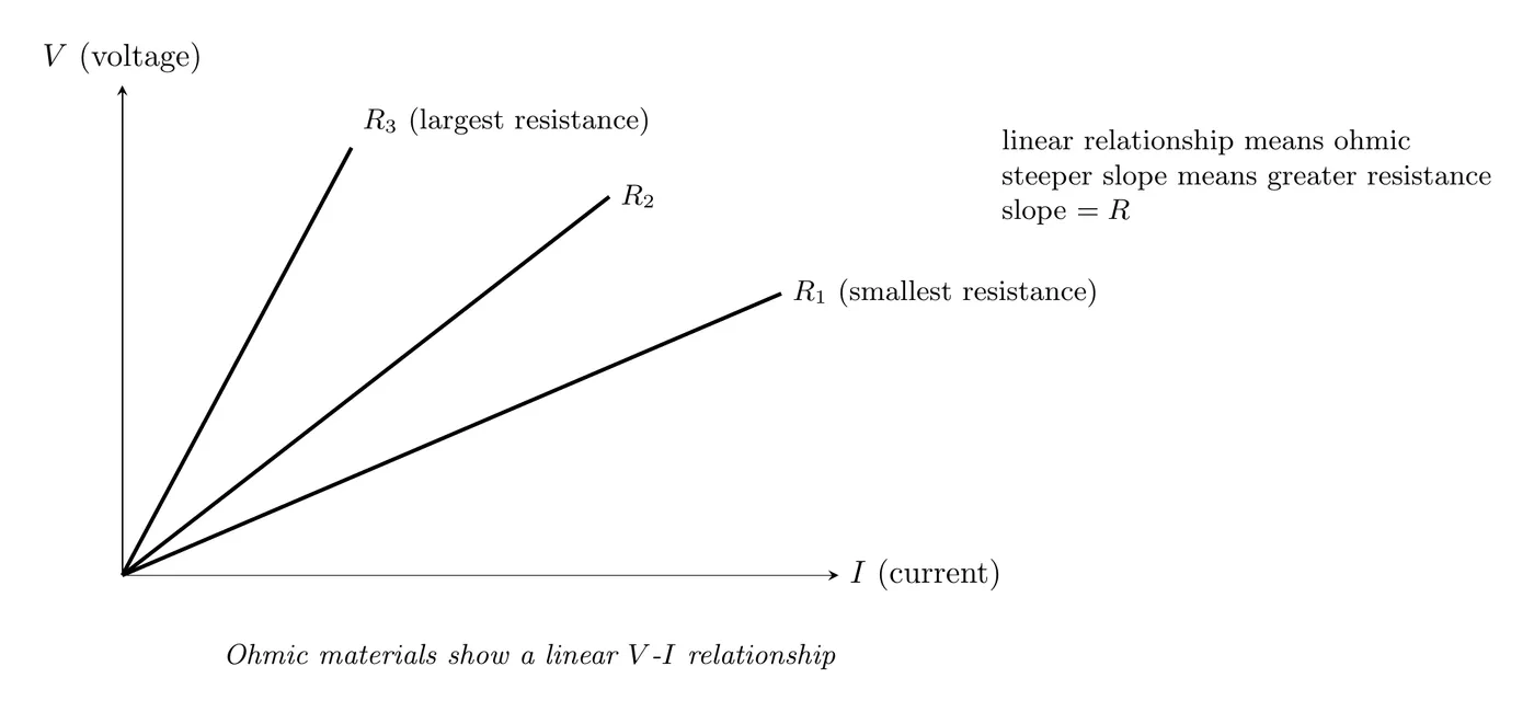
Examples of ohmic materials: metal wires at constant temperature, standard resistors, and most conductors under normal conditions.
Non-ohmic materials have a resistance that shifts with the voltage or current, so the vs. relationship comes out curved.
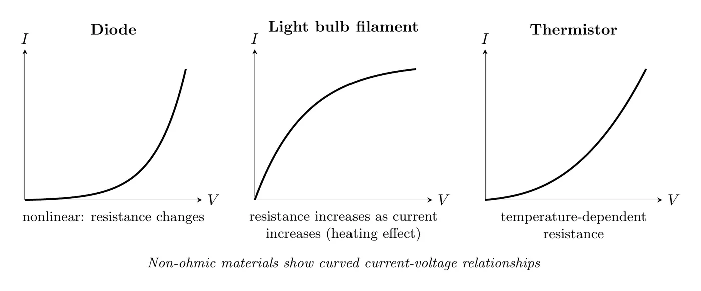
Examples of non-ohmic materials: diodes, light bulb filaments (whose resistance climbs as they heat up), transistors, and thermistors. A curved graph means the resistance depends on the operating conditions, so you can’t just plug in a constant ; you have to use at that point on the curve (not the slope).
The ideal ohmic material. For an ohmic material, the resistivity (and so the resistance) stays the same no matter the temperature, which is what keeps its vs. graph a straight line. Real conductors only come close to this, since their resistivity creeps up as they heat. But on the AP exam, resistors and lightbulbs are treated as ohmic unless the problem says otherwise, so you can use one constant for each.
Determining Resistance from Graphs
On a voltage vs. current graph, the slope is the resistance:
A steeper slope means a larger resistance, and a flatter slope means a smaller one.
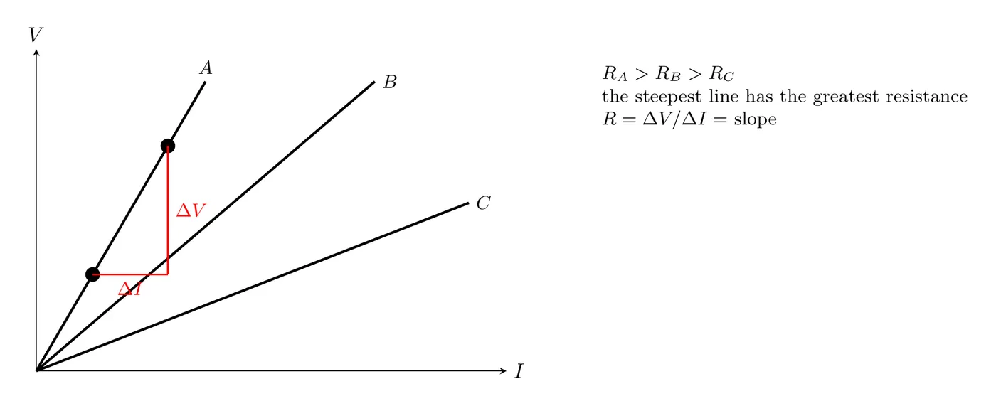
Watch which axis is which. The CED describes this graph the other way around: current on the vertical axis and potential difference on the horizontal axis, which is how you’d plot lab data where you set the voltage and measure the current. Then the slope is , so , and the steeper line has the smaller resistance.
Example (lab): To measure an unknown resistor, connect it to an adjustable power supply with an ammeter in series and a voltmeter in parallel across it. Set five different voltages, record the current at each, plot against , and draw a best-fit line through the data:
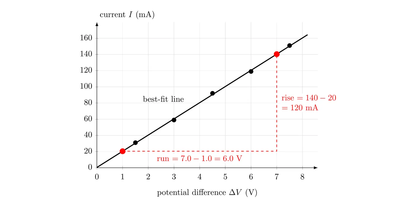
Read the slope from two points on the line, not from two data points: mA/V, which is 0.020 A/V. So Ω. The line also runs through the origin (to within the scatter of the data), as it should for an ohmic resistor.
Electrical Power
Power is the rate at which electrical energy gets transferred, converted, or dissipated in a circuit element:
where is power (W, watts), is the current through the element (A), and is the potential difference across it (V). One watt is one joule per second: .
Alternative forms. Combining with Ohm’s law gives two more. Substituting :
and substituting :
So the three forms are:
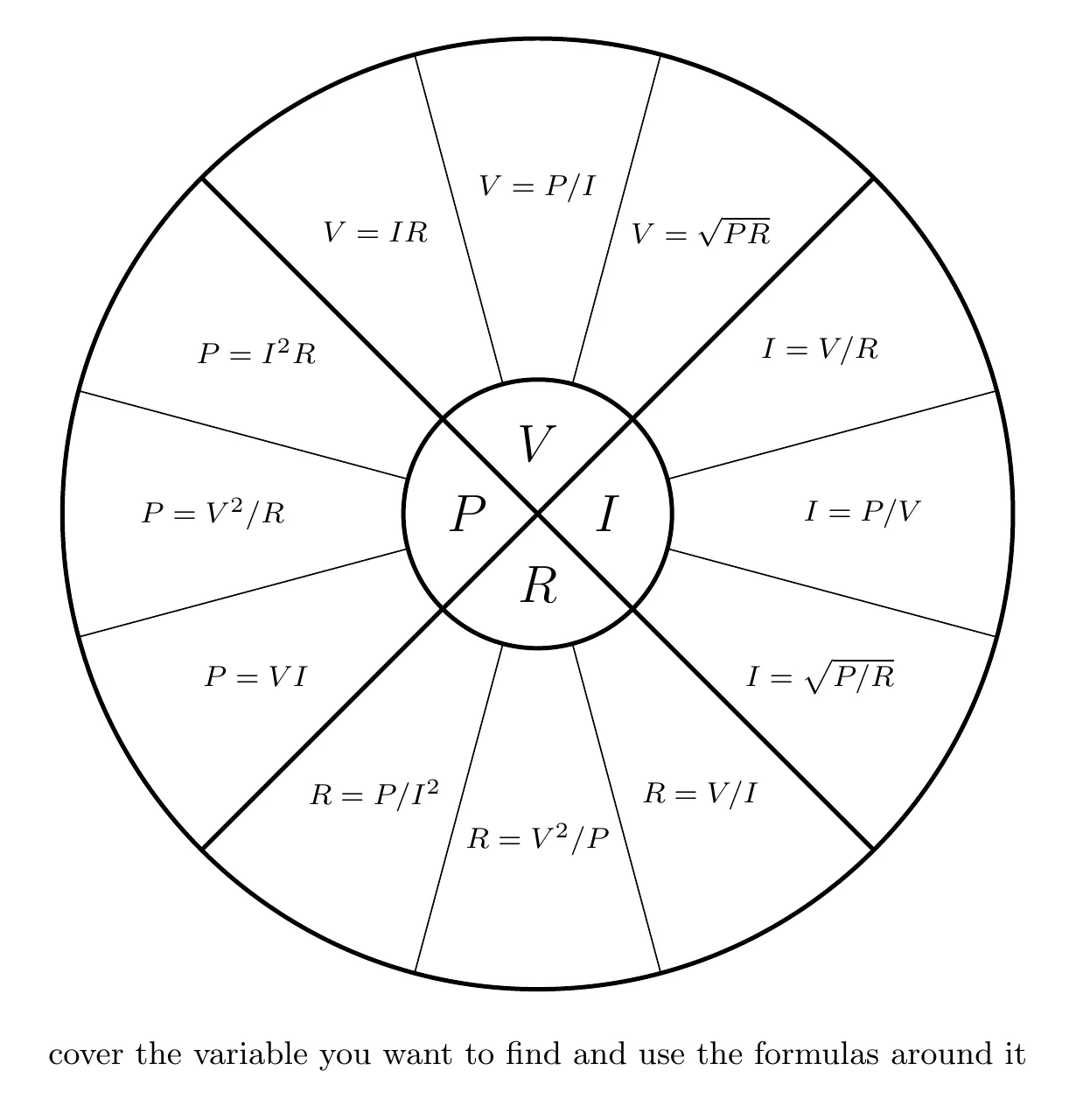
Pick whichever matches what you know: use if you have and , if you have and , and if you have and .
Only is on the AP equation sheet. and are derived from it with Ohm’s law, exactly as above.
Energy into, out of, and within a circuit. For a battery, is the rate it gives energy to the charges passing through it. For a resistor, it’s the rate the charges give that energy up. Energy is conserved, so the power the batteries supply always equals the total power used by everything else in the circuit.
Example: An 18 V battery drives a 6.0 Ω resistor and a 3.0 Ω resistor in series. The current is A. The 6.0 Ω resistor uses W and the 3.0 Ω resistor uses W. The battery supplies W, exactly . In series, the bigger resistor gets more of the power, since both have the same current and grows with .
Energy Dissipation in Resistors
When current runs through a resistor, electrical energy turns into thermal energy (heat). The energy dissipated over time is:
You see this everywhere: heating elements (toasters, space heaters) are built specifically to dump power as heat, light bulb filaments glow because they get hot, and in most other circuits the heat is just unwanted energy loss.
That thermal energy warms the resistor itself, and the warm resistor then heats the air and anything else around it. (In a real conductor the warming also nudges the resistance up, since resistivity rises with temperature.)
Why the electric bill is in kilowatt-hours. You pay for energy, not for current or for electrons. A kilowatt-hour is the energy used at 1 kW for one hour: J. A 1.5 kW space heater running for 4.0 h uses kWh, about J.
Lightbulb Brightness
A lightbulb’s brightness increases with the power it uses, so to compare bulbs, compare . It’s a qualitative tool: more power means brighter, and two bulbs using the same power glow equally.
Example: Three identical bulbs, each 4.0 Ω, are connected to an ideal 12 V battery as shown. Rank their brightness.

Bulb A is alone in its branch, so it has the full 12 V across it: W. Bulbs B and C share the other branch in series, so each gets half of the 12 V: W.
So A is the brightest, and B and C are equally bright, each with a quarter of A’s power. Now unscrew bulb B. Its branch opens, so C goes out too. Bulb A still has 12 V across it, so it stays exactly as bright as before: with an ideal battery, each parallel branch works on its own.
Example Problem: Resistance of a Coaxial Cable
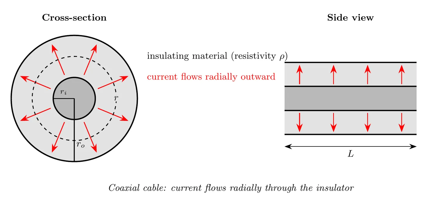
A coaxial cable is two concentric cylindrical conductors. The gap between the inner conductor (radius ) and the outer conductor (radius ) is filled with insulating material of resistivity , and the cable has length . Derive an expression for the resistance of the insulating material between the conductors.
Solution
The key insight: the current flows radially outward from the inner conductor to the outer one, and the geometry changes as you move outward, so you have to integrate.
Step 1: Set up a differential resistance. For a thin cylindrical shell at radius with thickness :
where is the area the current passes through at radius .
Step 2: Find that area. At radius , the current crosses a cylindrical surface whose area is the circumference times the length:
Step 3: Substitute.
Step 4: Integrate from the inner radius out to the outer one. The total resistance is all those shells added up:
Step 5: Do the integral. Since :
Step 6: Simplify with the log rule :
Sanity-checking the result: if goes up, goes up (makes sense). If goes up, goes down (also makes sense, since there’s more area for the current). And if goes up, meaning a thicker insulator, goes up (makes sense again).
Quick Reference: Formula Summary
Quantity | Primary formula | Alternative forms |
Resistance | ||
Ohm’s law | , | |
Power | , | |
Energy | , |
Problem-Solving Strategy
For Ohm’s law problems: figure out what you know (, , or ), figure out what you need, pick the form of the equation that uses your known variables, solve algebraically before plugging in numbers, and check that your units line up (volts, amperes, ohms).
For power problems: list what you know (, , , or some combination), choose the power formula that matches, then calculate and sanity-check (power should come out positive, in watts).
Conceptual Questions Worth Thinking Through
Why does resistance grow with length? A longer path means more collisions between electrons and atoms, so more opposition to the flow.
Why does resistance shrink with area? A bigger area means more pathways, so it’s easier for charges to get through and there’s less opposition.
What happens to power if you double the voltage across a resistor? From , doubling quadruples .
What happens to power if you double the current through a resistor? From , doubling also quadruples .
Common Mistakes
- Confusing resistivity () with resistance (). Resistivity is a material property (Ω·m); resistance belongs to a specific object (Ω). Related, but not the same.
- Using the wrong power formula. Match the formula to what you actually know. Don’t reach for when you only have and ; use .
- Forgetting to square. Both and have squares. Dropping them wrecks the answer.
- Assuming everything is ohmic. Light bulbs, diodes, and plenty of real devices are non-ohmic. Their resistance shifts with operating conditions, so you can’t carry a constant through the problem.
- Misreading the slope. On a V vs. I graph, a steeper slope means higher resistance. A lot of people instinctively think “steep means fast means low resistance,” but it’s the opposite.
- Reading an vs. graph like a vs. graph. When current is on the vertical axis, the slope is , so the steepest line has the smallest resistance. Check the axes before you read the slope.