

4.8 - Resistor Capacitor (RC) Circuits
Capacitors in Series and Parallel
When you wire several capacitors together, you can replace them with a single equivalent capacitance for analysis.
Capacitors in Series
The key property: series capacitors all carry the same charge on their plates. Here’s why. In a series connection, charge can’t pile up at the junctions between capacitors. When one capacitor picks up on one plate, it must have on the other, which induces on the next capacitor’s plate, and the chain continues.
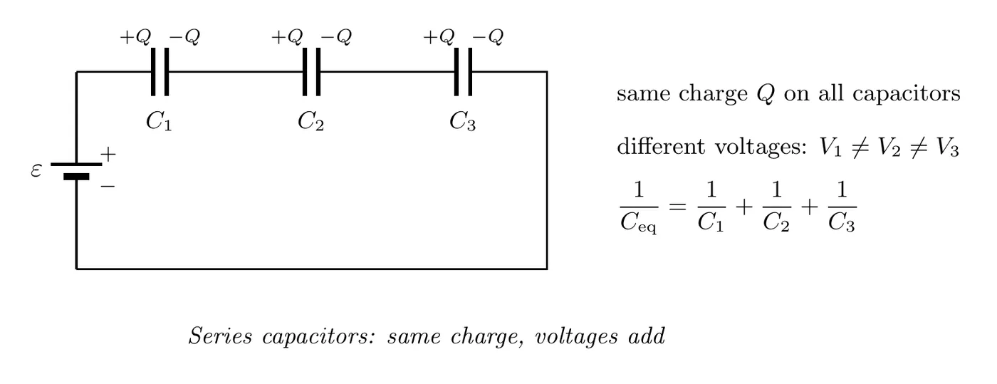
Note that this is the opposite of resistors in series, which just add.
Series always lowers the capacitance. for capacitors in series is less than the smallest capacitor in the chain. Each is positive, so their sum is bigger than any one of them. Physically, capacitors in series act like one capacitor with a wider plate gap, and drops as grows.
Example: a 3.0 μF capacitor and a 6.0 μF capacitor in series: , so μF, less than the 3.0 μF one.
Capacitors in Parallel
The key property: parallel capacitors all have the same voltage across them. That’s because they all connect directly to the battery terminals, so they all see the same potential difference. Each one can still store a different amount of charge, depending on its capacitance.
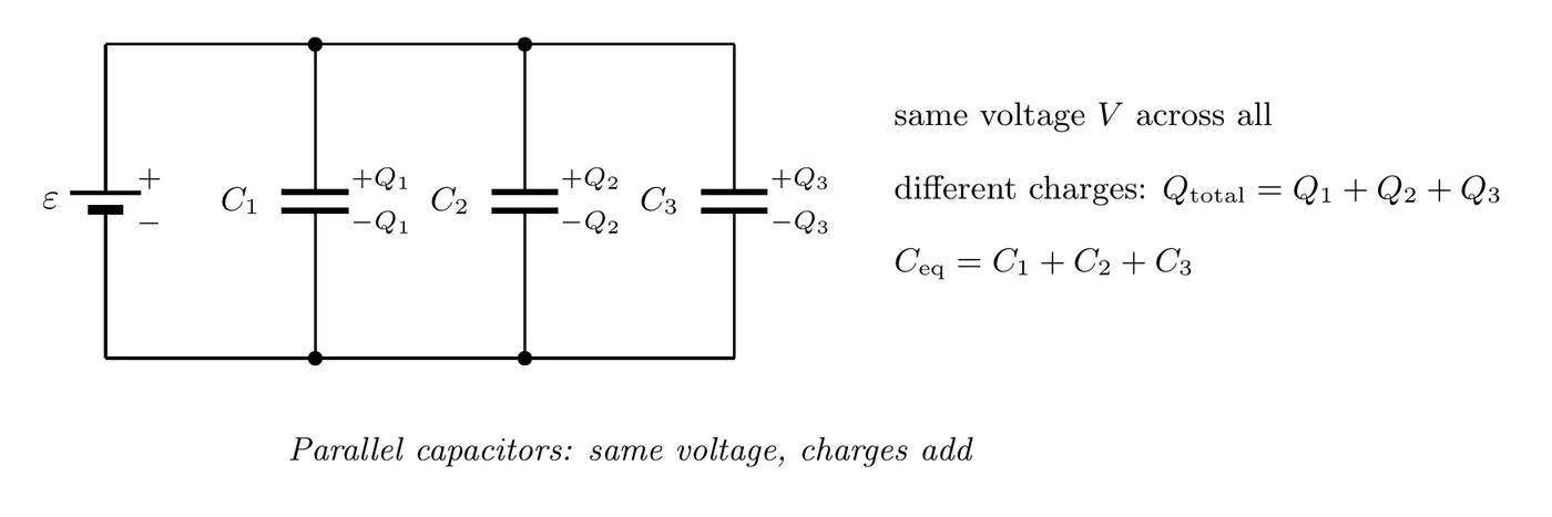
And this is the opposite of resistors in parallel, which use the reciprocal formula.
Comparison: Capacitors vs. Resistors
Configuration | Resistors | Capacitors |
Series | ||
Parallel |
Memory tip: the capacitor formulas are flipped compared to the resistor formulas.
On the AP equation sheet these are and .
Example Problem: A Capacitor Network
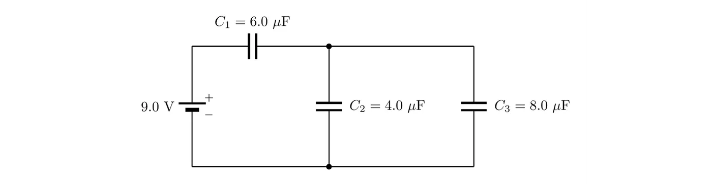
A 6.0 μF capacitor is in series with a parallel pair (4.0 μF and 8.0 μF), all connected to a 9.0 V battery. Once the capacitors are fully charged, find the charge on each one and the potential difference across each.
Solution
Step 1: Combine. The parallel pair adds: μF. That’s in series with :
Step 2: Total charge. . Capacitors in series carry the same charge, so has 36 μC, and so does the parallel pair as a whole.
Step 3: Split it up. V, which leaves V across the parallel pair. Then μC and μC. Check: μC.
Notice that , the smaller of the two series pieces (6.0 μF vs. 12 μF), takes the bigger share of the voltage. Same on a smaller means a bigger .
The RC Circuit Differential Equation
An RC circuit has both resistors and capacitors in it. How the charge and current behave comes out of a differential equation you get from Kirchhoff’s loop rule.
Picture a simple RC circuit: a battery (voltage ), a resistor (), and a capacitor (), all in series.
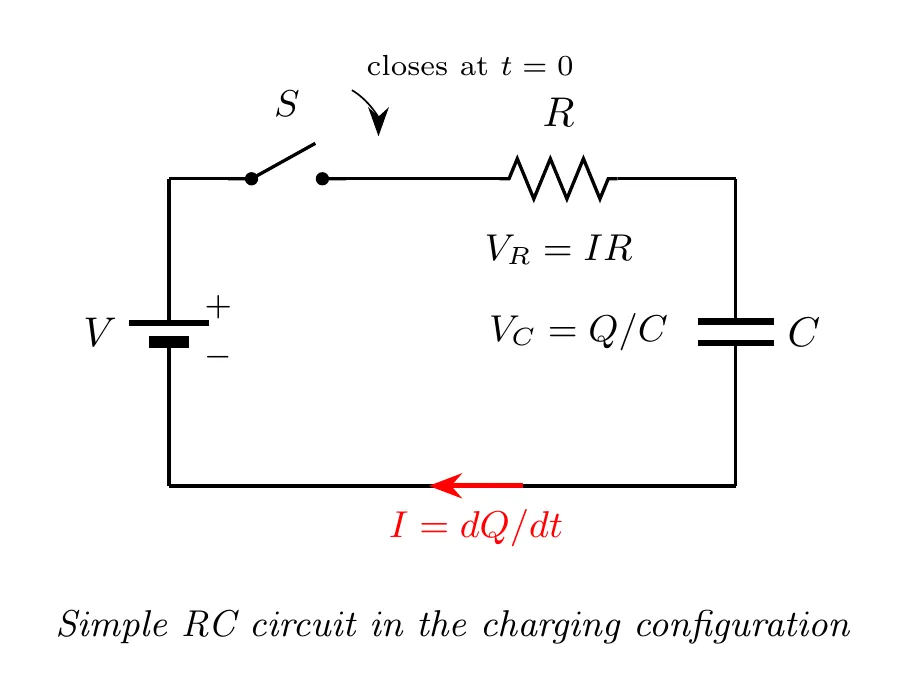
Applying the loop rule:
and since current is the rate of change of charge, :
That’s the fundamental differential equation for an RC circuit.
The CED writes it with for the battery and a lowercase for the charge, , which is the same equation. Each term is a potential difference: across the resistor and across the capacitor, and the loop rule says they add up to the battery’s emf at every instant. It isn’t on the equation sheet (only is), so be ready to build it from the loop rule.
Time Constant
The time constant tells you how fast the capacitor charges or discharges:
where (tau) is the time constant (s), is the resistance (Ω), and is the capacitance (F).
A bigger means slower charging and discharging, and a smaller means faster. After one time constant (), a charging capacitor has reached about 63% of its maximum charge, and a discharging one has lost about 63% of what it had. After five time constants (), the process is about 99% complete, which is close enough to done.
On the AP equation sheet: . With more than one resistor or capacitor, use the equivalent resistance of the path the capacitor charges or discharges through, and the equivalent capacitance. The units work out: .
Where 63% and 37% come from. At , a charging capacitor has of its final charge, and a discharging one has of its starting charge left.
Example: a 50 μF capacitor discharges through two 40 kΩ resistors in parallel. kΩ, so s. After 1.0 s the capacitor has 37% of its charge left, and after 5.0 s it’s essentially empty (under 1%).
Charging and Discharging Equations
Solving the differential equation gives you explicit formulas for charge, voltage, and current over time.
Charging a Capacitor
Starting from an uncharged capacitor ():
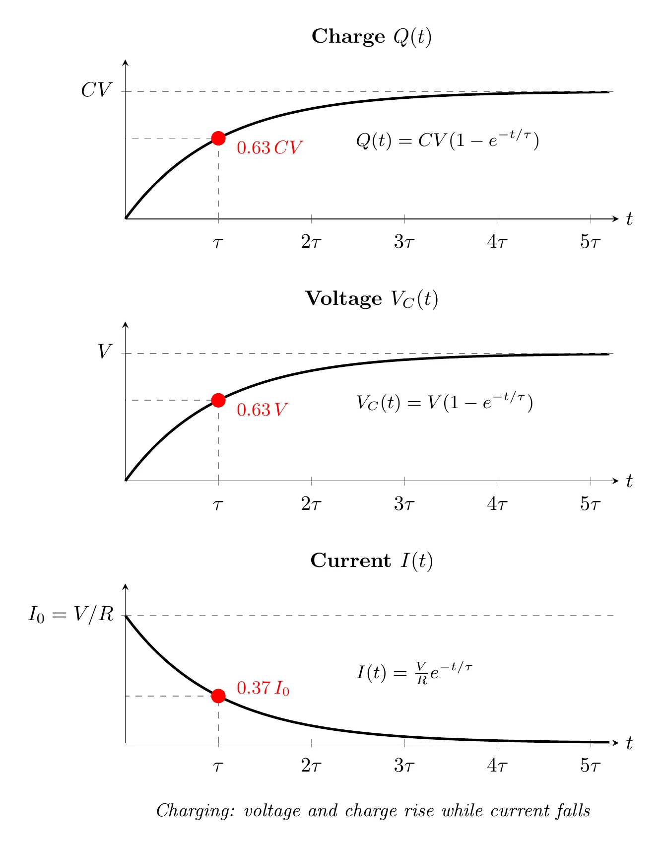
What’s happening: the charge and voltage climb exponentially toward their maximums while the current decays exponentially from its maximum down to zero. At the current is at its largest, , and as the current goes to zero, because the capacitor is fully charged and nothing more flows.
Getting the current from the charge. The current is how fast the charge on the capacitor grows, so differentiate :
And the capacitor’s voltage is just , which is why has the same shape as .
Right after the switch closes, the capacitor is uncharged, so . With no potential difference across it, it behaves exactly like a plain wire: an uncharged capacitor acts like a wire at , and charge flows onto its plates easily. That’s why the initial current, , is the same as if the capacitor weren’t there.
As it charges, the growing pushes back against the battery. The resistor is left with less potential difference (), so the current shrinks, so the charge builds more slowly. The charge, the capacitor’s voltage, the current, and the stored energy all change together and level off toward steady values instead of reaching them all at once.
After a long time (), has reached the battery’s , there’s no potential difference left across the resistor, and the current in the capacitor’s branch is zero. A fully charged capacitor acts like a break in the wire (an open circuit) for its branch.
Stored energy. The capacitor’s energy is (on the equation sheet). While charging, that’s : it starts at zero and climbs toward .
Discharging a Capacitor
Starting from a fully charged capacitor ():
where the negative sign just says the current now runs the opposite way.
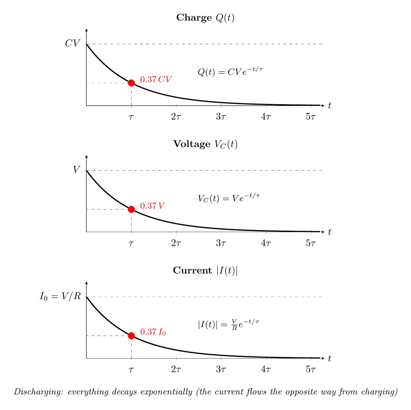
What’s happening: the charge, voltage, and current magnitude all decay exponentially toward zero, and the current runs backwards compared to charging. At the current magnitude is at its largest, , and as it goes to zero, with the capacitor fully drained.
The discharging differential equation. With the battery gone, the loop is just the capacitor and the resistor, and the capacitor is now the source: its potential difference pushes the current through . The current drains the capacitor, so the current’s magnitude is (the charge is decreasing, so is negative). The loop rule gives:
Separate the variables and integrate from the starting charge at :
With , that’s the discharging formula above. Its derivative, , is where the minus sign on the discharging current comes from.
As soon as discharging starts, the charge on the capacitor and the energy stored in it begin to drop. The charge, the potential difference, the current, and the energy all decrease together, quickly at first and then more and more slowly, because less charge means a smaller pushing the current. After many time constants, everything has reached the steady state: no charge, no voltage, no current.
Solving the Differential Equation
Starting from:
Step 1: Rearrange.
Step 2: Separate the variables.
Step 3: Integrate both sides. The left side needs a natural log:
Step 4: Solve for Q.
Step 5: Apply the initial condition. For charging, , so , meaning . Therefore:
which is where the exponential charging formula comes from.
Example Problem: Charging a Capacitor Through a Resistor
An uncharged 40 μF capacitor is connected in series with a 50 kΩ resistor and a 9.0 V battery, and the switch closes at . Find (a) the time constant, (b) the initial current, (c) the charge, the capacitor’s voltage, and the current at s, and (d) how long the capacitor takes to reach 90% of its final charge.
Solution
(a) s.
(b) At the capacitor acts like a wire, so A, or 0.18 mA.
(c) The final charge is C, and :
Check with the loop rule: V.
(d) Set . Then , so and:
Example Problem: Windshield Wiper Timer Circuit
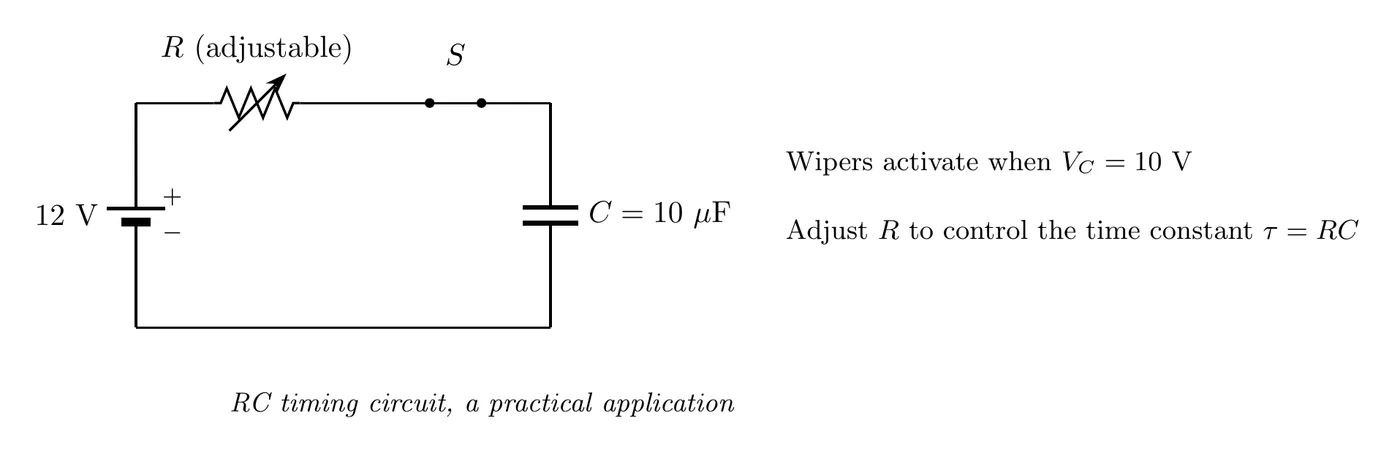
A windshield wiper uses an RC circuit for its timing. The circuit has a variable resistor (a rheostat) and a capacitor of μF, with a 12 V battery. The wipers fire when the capacitor’s voltage hits V while charging. What resistance gives a 10-second delay between wiper cycles?
Solution
Given μF F, V, V, and s, find .
Use the charging voltage equation:
Solve for :
Take the natural log of both sides:
Find R from :
So you’d set the resistance to about 558 kΩ.
Reading the result: a bigger resistance means a bigger time constant means a longer delay. That’s exactly how variable-speed windshield wipers work. Turning the rheostat changes the resistance, which smoothly adjusts the timing from fast wiping (low R) to slow wiping (high R).
Alternative Formula for Finding R
You can derive a direct formula for the general “find the resistance that hits a target voltage at a specific time” problem. Starting from:
which gives:
That hands you the resistance directly for a charging circuit.
Example Problem: A Capacitor in One Branch
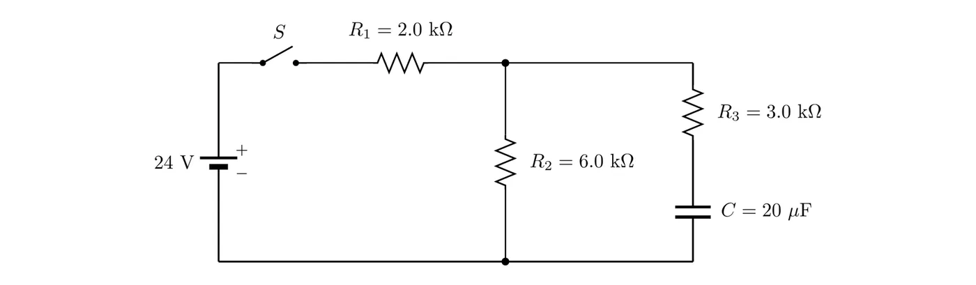
In the circuit below, the capacitor starts uncharged and the switch S closes at . Find (a) the current in each resistor just after the switch closes, and (b) the current in each resistor, the charge on the capacitor, and its stored energy after a long time. (c) Then the switch is opened again. Find the time constant of the discharge and the current just after the switch opens.
Solution
(a) Just after closing: the uncharged capacitor acts like a wire, so is simply in parallel with : kΩ. Adding in series gives 4.0 kΩ in total:
The parallel part has V across it, so mA and mA. Check: mA.
(b) After a long time: the capacitor is fully charged and acts like a break in its branch, so . Now and are simply in series: mA. With no current in there’s no potential difference across it, so the capacitor has the same potential difference as : V, not the full 24 V.
(c) Opening the switch: the battery and are cut out of the circuit, so the capacitor discharges around the loop through and , which are now in series: kΩ.
That current then decays as . In it still flows the same way as before (top to bottom), but in it reverses, because charge is now leaving the capacitor instead of arriving. After about s the capacitor is essentially empty and every current is zero.
Summary of Key Formulas
Capacitor combinations:
Configuration | Formula |
Series | |
Parallel |
Time constant:
Charging (starting uncharged):
Quantity | Formula |
Charge | |
Voltage | |
Current |
Discharging (starting fully charged):
Quantity | Formula |
Charge | |
Voltage | |
Current |
Practical Applications
Timing circuits: windshield wipers (as above), turn signals in cars, digital clocks and timers, and delay circuits.
Filters: audio crossovers (splitting high and low frequencies), power supply smoothing, and signal conditioning.
Flash photography: the capacitor charges slowly, then dumps its charge fast to fire the flash, with an RC circuit controlling the charging time.
Touch screens: capacitive sensing runs on RC time constants, since your finger changes the capacitance and the timing circuit picks it up.
Behavior at Key Times
Time | Charging | Discharging |
, | , | |
, | , | |
, | , | |
, | , | |
, | , |
Rule of thumb: after five time constants, the process is basically finished (over 99%).
Common Mistakes
- Mixing up the series and parallel formulas for capacitors. Capacitors combine backwards from resistors. Series capacitors use the reciprocal formula, parallel capacitors just add. Don’t reach for the resistor formulas.
- Messing up the time constant units. Resistance in ohms and capacitance in farads gives a time constant in seconds. Watch for μF (microfarads), which need converting to farads first.
- Grabbing the wrong charging or discharging formula. Charging formulas have a term. Discharging formulas have just . Check the initial conditions to see which one you need.
- Sign errors solving the exponential. When solving , remember , so . That negative sign is what makes the answer come out positive when .
- Confusing the capacitor voltage with the battery voltage. In an RC circuit, is the battery’s fixed voltage, while is the capacitor’s voltage, which changes over time. They’re only equal once the capacitor is fully charged.
- Assuming a charged capacitor always ends up with the battery’s full voltage. In a circuit with several branches, a fully charged capacitor matches the potential difference across whatever it’s in parallel with, which can be less than the battery’s emf.