

4.6/4.7 - Kirchhoff’s Loop Rule and Kirchhoff’s Junction Rule
Introduction
Kirchhoff’s rules pin down how current moves through circuits and how voltage changes around loops. They’re what you need for complex circuits with multiple batteries and multiple current paths. Both rules come straight out of conservation principles: the loop rule is conservation of energy, and the junction rule is conservation of charge.
Kirchhoff’s Loop Rule (Voltage Law)
The rule: the sum of all potential differences around any closed loop equals zero.
The idea behind it: travel all the way around a loop and you end up back at the same potential you started at, so the total change has to be zero. Put another way, the energy you gain from the batteries equals the energy you lose across the resistors.
For a single loop:
or more generally, energy gained equals energy lost:
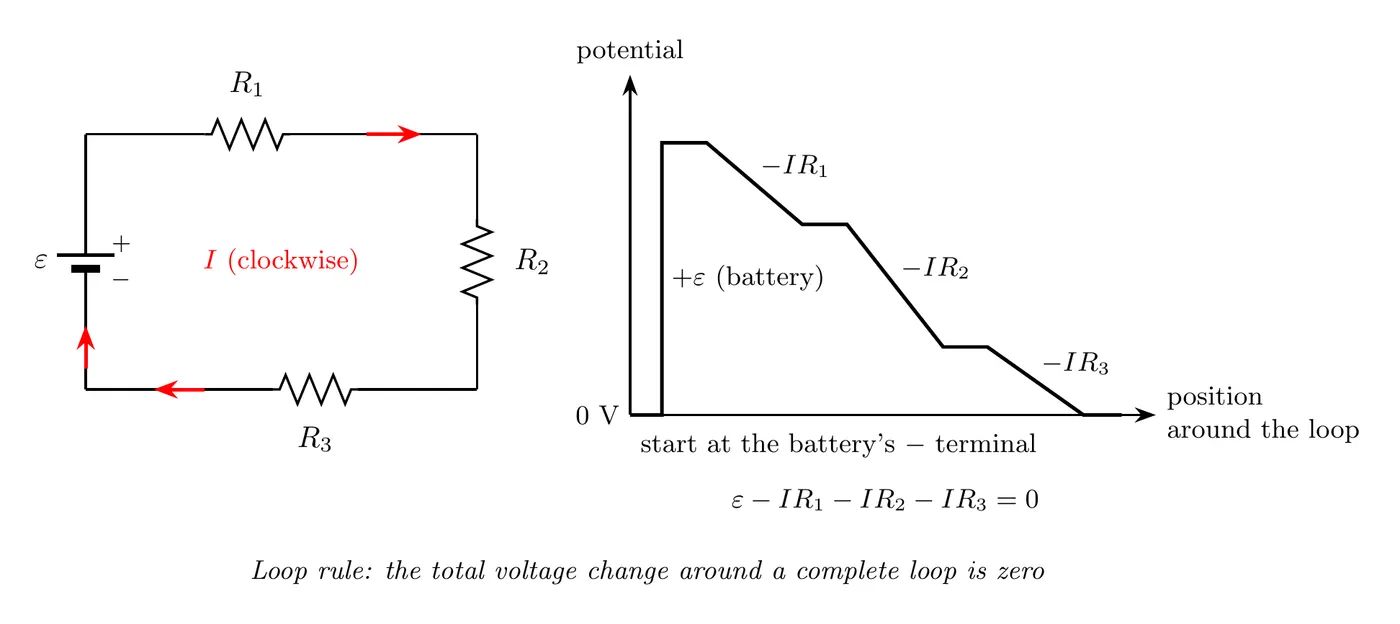
The energy picture. When a charge moves through a potential difference , its electric potential energy changes by:
That one is on the equation sheet; the loop rule itself isn’t, and the CED writes it as . A battery raises the potential energy of the charge passing through it, and each resistor takes that energy back out. Example: a 12 V battery drives 1.0 A through a 4.0 Ω resistor and an 8.0 Ω resistor in series. Follow 0.50 C of charge once around the loop: it gains J in the battery, then loses J in the 4.0 Ω resistor and J in the 8.0 Ω resistor. It gets back to its starting point with exactly the energy it started with, which is the loop rule: .
The graph above tells the same story as electric potential vs. position around the loop: the battery is a step up, each resistor is a slope down, ideal wires are flat, and you finish at the same potential you started from.
Sign Conventions for the Loop Rule
Getting the sign right on each term is the whole game. The sign depends on whether you gain or lose potential as you pass through the element.
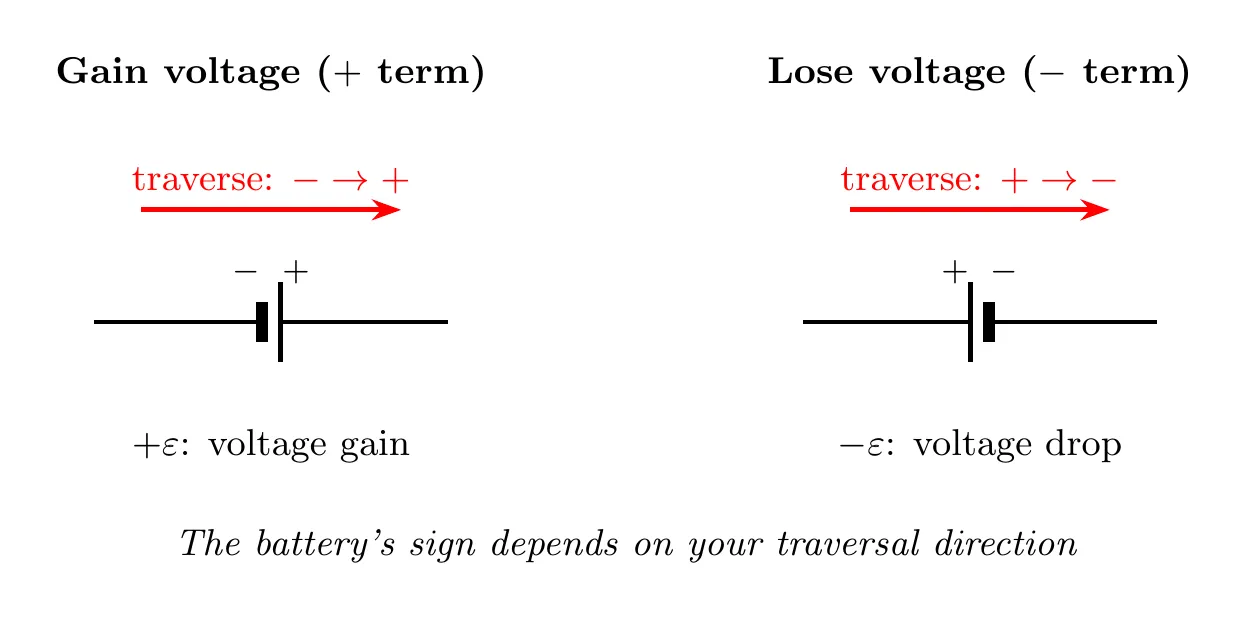
Batteries. It depends on which way you’re traveling relative to the EMF.
Traversal direction | Sign | Reasoning |
− to + (with the EMF) | + (gain) | Moving from low to high potential |
+ to − (against the EMF) | − (loss) | Moving from high to low potential |
Resistors. It depends on which way the current runs through them.
Traversal direction | Sign | Reasoning |
With the current | − (drop) | Moving toward decreasing potential |
Against the current | + (gain) | Moving toward increasing potential |
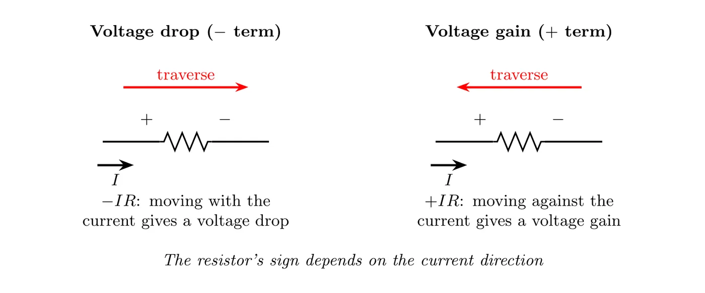
The standard approach: mark the end of the resistor where the current enters as +, and the end where it exits as −. That captures the voltage drop across the resistor.
Kirchhoff’s Junction Rule (Current Law)
The rule: the total current flowing into a junction equals the total current flowing out.
or equivalently , counting currents entering as positive and currents leaving as negative.
The idea behind it: charge is conserved, so it can’t pile up at a junction. Whatever flows in per second has to flow out per second.
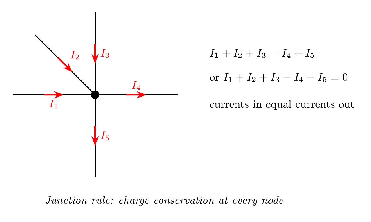
In circuits with several junctions, apply the rule at each one to generate more equations. A useful shortcut: with junctions, you typically only need independent junction equations, since the last one is redundant.
Example: in the junction picture above, if A, A, and A flow in and A flows out, then A has to flow out along the last wire.
In lab terms: put an ammeter in every wire at a junction, and the readings for the currents going in add up to the readings for the currents coming out. Like the loop rule, the junction rule isn’t on the equation sheet, so know it as .
Problem-Solving Strategy
Step 1: Draw and label the circuit. Mark all the known values (voltages, resistances), assign a current variable to each branch even if you don’t know its value yet, and just assume a direction for each current. If you guess wrong, you’ll get a negative answer, and that’s fine.
Step 2: Mark the voltage polarities. On each resistor, put + where the current enters and − where it exits. On each battery, mark the + and − terminals.
Step 3: Apply the junction rule. Write an equation at each junction, setting currents in equal to currents out.
Step 4: Apply the loop rule. Pick enough loops to get equations for all your unknowns, traverse each loop in one consistent direction (clockwise or counterclockwise), apply the sign conventions as you go, and set .
Step 5: Solve the system by substitution or elimination.
Step 6: Interpret the results. A negative current just means your assumed direction was backwards, so the current actually flows the other way. Then double-check that the currents satisfy conservation at the junctions.
Example Problem 1: Loop Rule Application
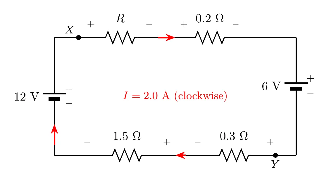
In the circuit below, the current is A. Find the potential difference between points X and Y.
Solution
Step 1: Apply the loop rule, traversing clockwise (with the current), starting from the bottom left:
Where each sign comes from: V because you cross that battery from − to + (a gain), V because you cross that one from + to − (a loss), and every resistor term is negative because you’re moving with the current through each of them (a drop).
Step 2: Simplify.
Step 3: Find the voltage from X to Y. Between the two points you pass the 6 V battery, the 0.2 Ω resistor, and the 1 Ω resistor. Summing the voltage changes from Y to X:
So the potential difference from X to Y is 8.4 V, with X at the higher potential.
Verification, going the other way around from X to Y:
which gives V, matching.
Graphing the potential around the loop. Call the 12 V battery’s negative terminal 0 V and walk clockwise, with the current. You go up 12 V through the battery, so X is at 12 V. Then you drop V across and 0.4 V across the 0.2 Ω resistor, down 6 V through the 6 V battery (so Y is at 3.6 V), and finally down 0.6 V and 3.0 V across the bottom resistors, back to 0 V.
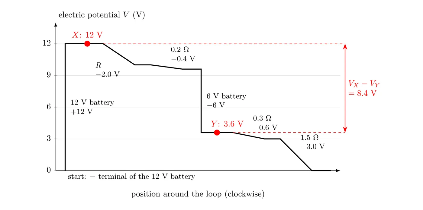
The graph gives V right off the vertical axis, matching the answer above. Notice that the 6 V battery is a step down: you cross it from to , so the charge loses potential energy there (that battery is being charged).
Example Problem 2: Junction and Loop Rules Together
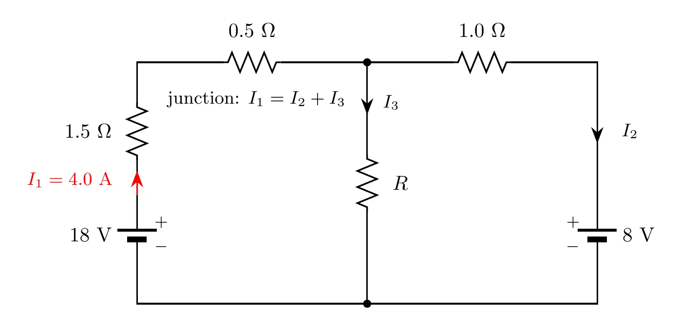
In the circuit below, the current through the 18 V battery is 4.0 A. Find the unknown resistance .
Solution
Step 1: Pick loops and apply the loop rule.
Loop 1, containing the 18 V battery, its two resistors, and the unknown resistor:
Loop 2, containing the 8 V battery and the unknown resistor:
Step 2: Solve the system. Loop 1 gives the voltage across the unknown resistor (10 V). Put that into Loop 2 to find the current in the 8 V branch, then use the junction rule at the top junction to find the current through the unknown resistor:
So the unknown resistance is 5.0 Ω. The 2.0 A in the 8 V branch flows into that battery’s positive terminal, so the 18 V battery is charging it.
Tips for Success
Choosing current directions. Don’t stress about guessing wrong. Assume any direction for the unknown currents. If your answer comes out negative, the real current just runs the other way, and the magnitude is still correct.
Choosing loops. You need as many independent equations as you have unknowns. Not every loop is independent, since some are just combinations of others. For unknown currents you generally need about equations total, mixing junction and loop equations. Choose loops that actually include the unknown elements, favor simpler loops with fewer elements, and make sure the loops you pick are independent.
Staying consistent. Mark your polarities clearly before writing any equations, pick a direction (clockwise or counterclockwise) and stick with it for each loop, and track your signs carefully.
Common Scenarios
Multiple batteries. They can point the same way (voltages add) or fight each other (voltages subtract). Just apply the loop rule as usual and be careful with the signs.
Parallel resistors inside a bigger circuit. They share the same voltage (that’s what parallel means), their currents add at the junctions, and sometimes you can simplify things by collapsing them into an equivalent resistance first.
Summary of Kirchhoff’s Rules
Rule | Principle | Equation | Where it applies |
Loop rule | Energy conservation | Around any closed loop | |
Junction rule | Charge conservation | At any junction or node |
Sign conventions in a nutshell. For batteries: traversing − to + is a gain (+), traversing + to − is a loss (−). For resistors: traversing with the current is a drop (), traversing against the current is a gain ().
Common Mistakes
- Wrong signs in the loop equations. Track carefully whether you’re gaining or losing voltage. Flipped battery or resistor signs are the most common error by far.
- Not marking polarities on the resistors. Before writing any loop equation, mark + and − on each resistor based on the current direction. It kills a lot of sign errors.
- Not writing enough equations. You need as many independent equations as unknowns. Three unknown currents means three equations, mixing junction and loop rules.
- Choosing dependent loops. Not every loop gives you new information. The outer loop equation might just be the sum of two inner ones. Pick your loops thoughtfully.
- Forgetting the junction rule. People often lean entirely on the loop rule and end up short on equations. Remember to also apply the junction rule wherever currents split or combine.