

4.5 - Compound Direct Current Circuits
Introduction
Every circuit in this unit is a direct current (DC) circuit, meaning a constant voltage source (like a battery) pushes current in one direction. The elements can be wired three ways: in series (one single path), in parallel (multiple paths), or in some combination of the two.
Series Circuits
A series circuit forces the charge through every element one after another. There’s only one path, so the current has no choice. Think of runners on a track where everyone has to follow the same single lane with no shortcuts.
The precise test: two elements are in series only if every charge that passes through one has to pass through the other, with no junction between them where the current could split off.
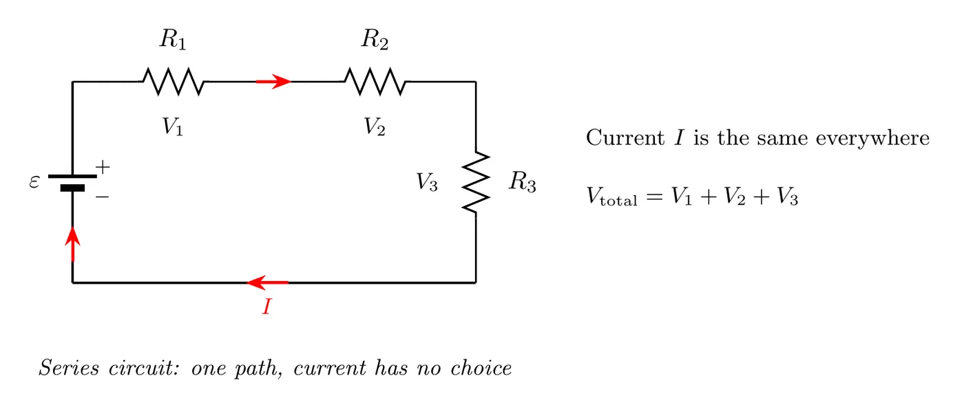
Current is the same through every element, since there’s only one path:
Voltage adds up across the elements, with the total drop equal to the battery voltage:
If all the resistors happen to be identical, the voltage splits evenly, so .
Equivalent resistance just adds:
On the AP equation sheet: .
Upsides and downsides. Series circuits are simple to design, they act as a built-in safety mechanism (if one element fails the circuit opens, preventing an overload), and the higher equivalent resistance keeps the total current low. But if one element fails, the entire circuit dies, so every element effectively acts as a switch for the whole thing, which makes series wiring impractical for household use. Old Christmas tree lights were wired in series, which is why one dead bulb killed the whole strand.
Parallel Circuits
A parallel circuit gives the current multiple paths. Each element connects straight to the voltage source, forming independent legs. Think of multiple lanes on a highway, where charge gets to pick a lane.
The precise test: elements are in parallel when each one connects across the same two junctions, so charge can take one path or the other and every path has the same potential difference across it.
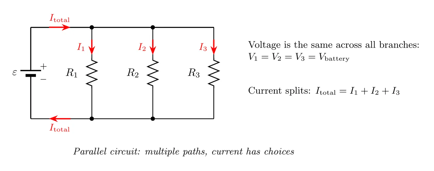
Voltage is the same across every parallel element, since they all hook directly to the battery terminals:
Current splits among the branches, with more current taking the lower-resistance paths:
Equivalent resistance uses a reciprocal formula, so the resistances do not just add:
On the AP equation sheet: . The two-resistor shortcut below comes straight from it.
For exactly two resistors there’s a shortcut:
The key insight: the equivalent resistance is always smaller than the smallest individual resistance. Adding more parallel paths makes it easier for current to get through.
Example: a 6.0 Ω resistor alone is 6.0 Ω. Put a second 6.0 Ω resistor in parallel with it and Ω; a third makes it 2.0 Ω. Each new path gives the charge another way through, so the battery’s total current goes up, even though the current in each resistor stays the same.
Upsides and downsides. If one element fails, the others keep working, each element runs independently, and you can add or remove branches without disturbing anything else, which is why parallel is the standard for household wiring. The trade-offs are more complicated wiring, a higher total current (so you can overload things by plugging in too much), and the need for protection like breakers and fuses. It’s why you can flip off the kitchen light without the rest of the house going dark.
Comparison: Series vs. Parallel
Property | Series | Parallel |
Current | Same through all | Splits: |
Voltage | Adds: | Same across all |
Equivalent R | ||
If one fails | Everything stops | The others keep going |
Adding an element | Raises | Lowers |
Example Problem: A Combination Circuit
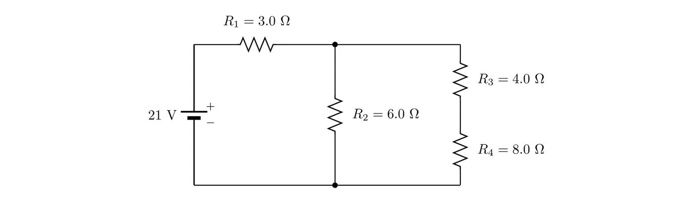
Find the current in each resistor and the potential difference across each one.
Solution
Step 1: Collapse the circuit from the inside out. and are in series (no junction between them), so together they’re Ω. That 12 Ω branch is in parallel with , since both connect across the same two junctions:
That 4.0 Ω is in series with , so Ω.
Step 2: Find the total current. A. All of it goes through , so V.
Step 3: Work back out. The parallel part gets the rest of the battery’s potential difference: V. That full 12 V is across and also across the and branch:
Then V and V.
Check. At the junction, A. Around the loop through the battery, , , and : . And the battery supplies W while the resistors use W.
Ideal vs. Non-Ideal Components
Ideal assumptions (the default). An ideal battery has no internal resistance and holds a constant voltage no matter how much current you draw, so its EMF always equals its terminal voltage. Ideal wires have zero resistance and no voltage drop along them. An ideal ammeter has zero resistance (it doesn’t impede the current), and an ideal voltmeter has infinite resistance (it draws no current).
When you can ignore the wires. Good conducting wires have tiny resistance compared with everything else, so treating them as zero barely changes the answer. Example: 1.0 m of copper wire with a radius of 1.0 mm has Ω. Next to a 100 Ω resistor that’s about 0.005%, so ignore it. But you can only ignore the wires if something else in the circuit has resistance. Connect that same wire straight across an ideal 1.5 V battery and the wire is the only resistance there is: , about 280 A. (A real battery’s internal resistance would hold the current lower, but either way the wire is no longer negligible.)
One setup the AP exam leaves out: batteries with different potential differences connected directly in parallel, with nothing between them. A circuit like Example Problem 2 in topic 4.6/4.7, where each battery sits in its own branch with resistors, is an ordinary Kirchhoff’s rules problem.
Non-ideal battery. Real batteries have internal resistance (), which causes a voltage drop whenever current flows.
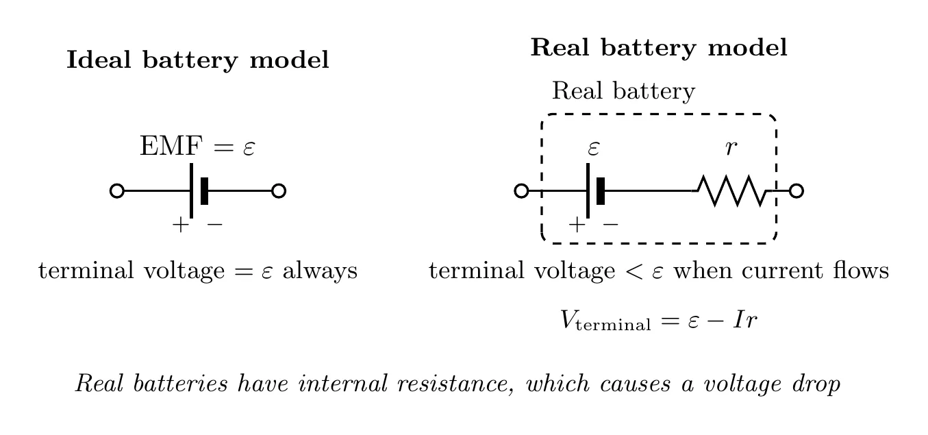
For a non-ideal battery:
where is the voltage across the terminals (V), is the battery’s EMF (V), is the current through the battery (A), and is the internal resistance (Ω).
Reading it: is the ideal voltage the battery wants to deliver, is the voltage lost inside the battery itself, and is what you’d actually measure across the terminals. It matters most when you’re drawing a lot of current, when the battery is old or weak (higher internal resistance), or when you need a really stable voltage.
What the emf actually is. With no current in the battery, , so the terminal voltage equals . That’s the definition: the emf is the potential difference across the terminals when there’s no current in the battery, which is what an ideal voltmeter reads across a battery that isn’t connected to anything else. isn’t on the equation sheet; it comes from treating the internal resistance as a resistor in series with an ideal battery.
Example: A battery with V and internal resistance Ω is connected to a 4.0 Ω resistor. The internal resistance is in series with the external one, so the total is Ω:
A voltmeter across the terminals reads 9.0 V before the resistor is connected and 8.0 V after. The missing 1.0 V is used up inside the battery, which turns W into heat in the battery itself. The battery’s emf supplies W in total: 16 W to the resistor and 2.0 W inside. (On the AP exam, batteries are ideal unless the problem gives you an internal resistance.)
Measuring Instruments
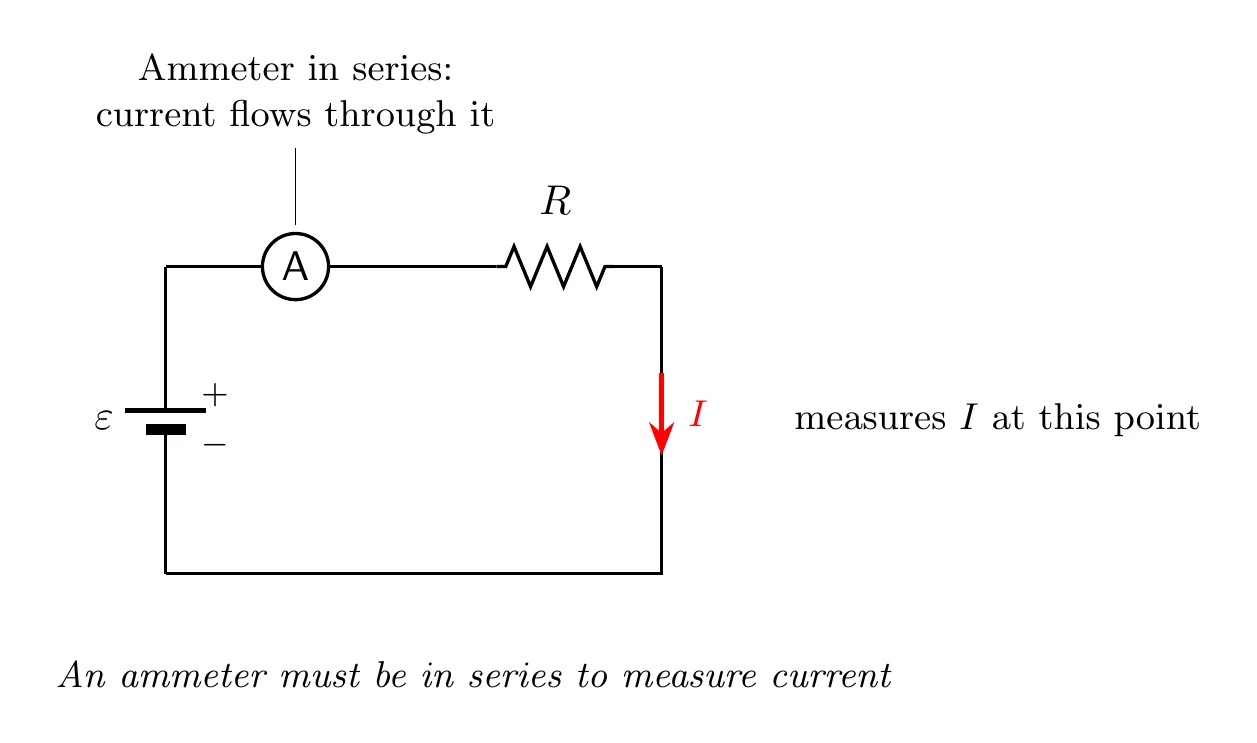
Ammeter (measures current). It reads the current at a specific point, so it has to go in series with the element you’re measuring, since the current needs to actually flow through it. That’s true in any circuit configuration. Ideally it has zero resistance and acts like a plain wire.
Voltmeter (measures voltage). It reads the potential difference between two points, so it has to go in parallel across the element, connecting to both sides without interrupting the circuit path. Ideally it has infinite resistance and draws no current.
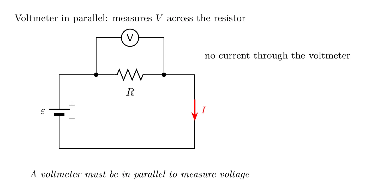
So: ammeter in series (it interrupts the current path), voltmeter in parallel (it spans across the element). Wire them backwards and there’s trouble. An ammeter in parallel draws a huge current and probably destroys itself. A voltmeter in series turns the circuit into an open circuit, since its infinite resistance blocks the current.
Real (nonideal) meters change what they measure. A real ammeter has a little resistance, so putting it in series lowers the current a bit: an ammeter with 1.0 Ω of resistance in series with a 4.0 Ω resistor and a 10 V battery reads A instead of 2.5 A. A real voltmeter has a large but finite resistance, so it draws a little current and acts like an extra resistor in parallel with whatever it’s measuring. Unless a problem says otherwise, AP questions treat every meter as ideal.
Example: Two 10 kΩ resistors are in series with a 12 V battery, so each one should have 6.0 V across it. You check with a cheap voltmeter whose resistance is only 10 kΩ, connected across the bottom resistor:
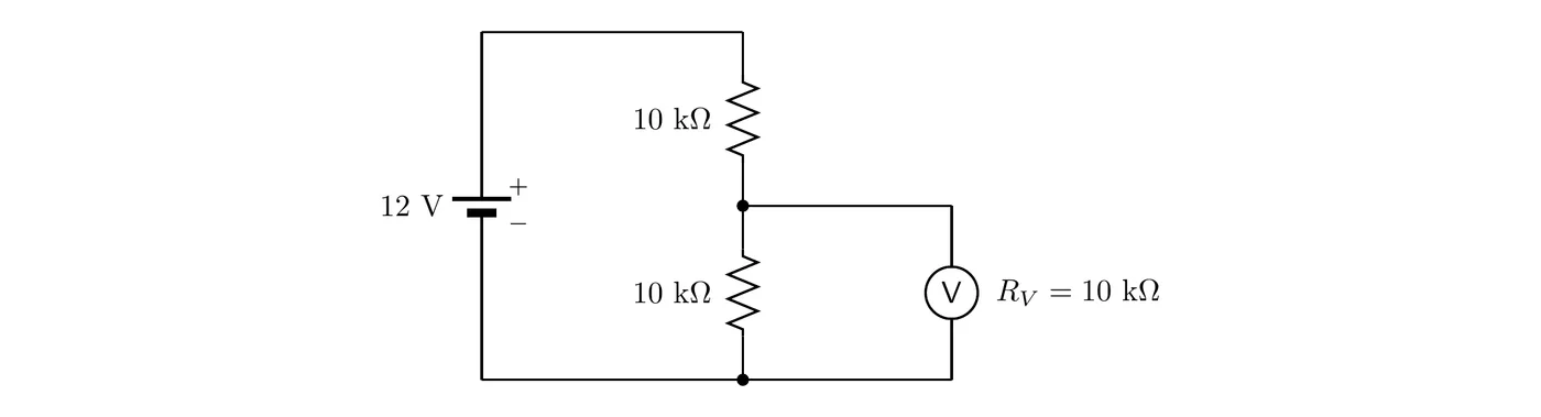
The voltmeter and the bottom resistor are now in parallel: kΩ. The total is kΩ, so mA, and the voltmeter reads V instead of 6.0 V. Hooking up the meter changed the very voltage it was trying to measure. A good voltmeter has a resistance far larger than anything in the circuit, so it barely disturbs it.
Example Problem: Battery Internal Resistance
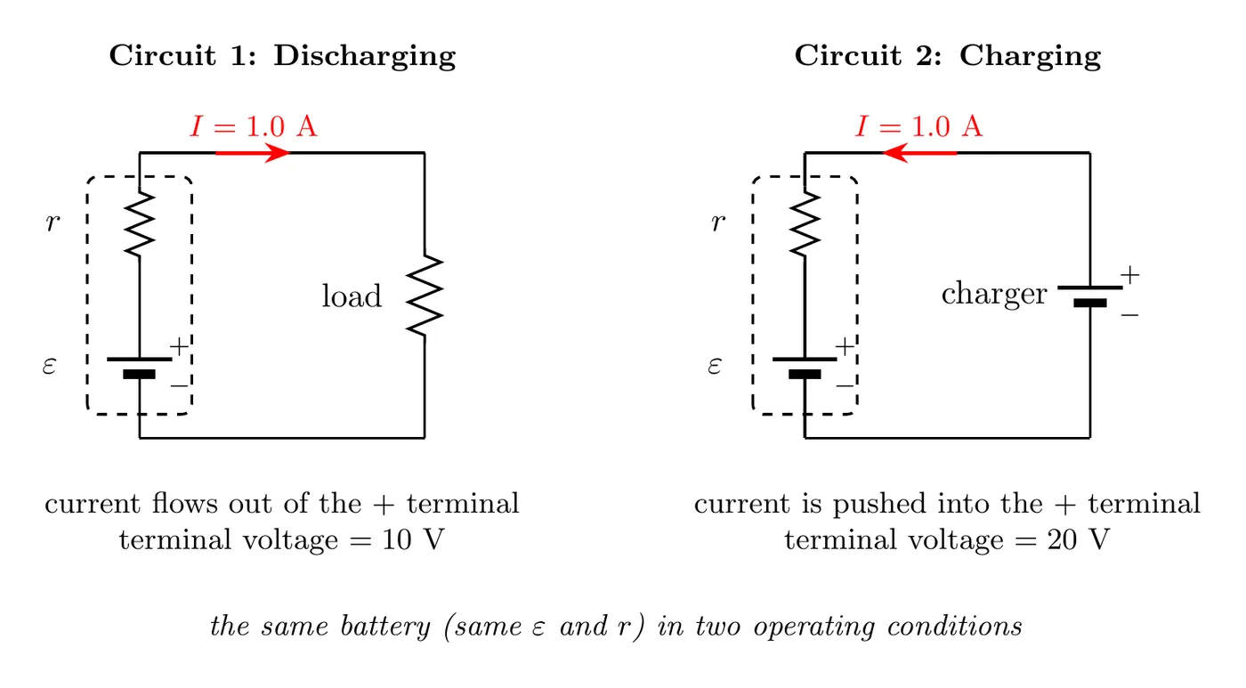
Two circuits each contain a battery with the same EMF () and internal resistance (). The current in each battery is 1.0 A, but it flows in opposite directions. The potential differences across the battery terminals are 10 V and 20 V. Find (a) the EMF and (b) the internal resistance.
Solution
Both cases use , but the sign on the term flips depending on which way the current runs relative to the EMF.
Circuit 1 (discharging, current flows with the EMF). The terminal voltage comes out less than the EMF:
Circuit 2 (charging, current flows against the EMF). An external source is pushing current backwards into the battery, so the terminal voltage comes out more than the EMF:
Solve the system. Subtract Equation 1 from Equation 2:
So the internal resistance is 5 Ω. Now substitute back into Equation 1:
So the EMF is 15 V. Checking against Equation 2: , which works.
Reading the result: the battery’s ideal voltage is 15 V. When it’s discharging (1 A flowing out), the internal resistance eats 5 V, leaving 10 V at the terminals. When it’s charging (1 A flowing in), the internal resistance adds to the voltage instead, pushing the terminals up to 20 V.
Problem-Solving Strategy for Circuits
Start by identifying the configuration (series with one path, parallel with multiple paths, or a combination). Then write down the relationships you know: in series, current is the same, voltages add, and resistances add; in parallel, voltage is the same, currents add, and the reciprocals of the resistances add. Apply Ohm’s law to each element () and to the whole circuit (). Check for non-ideal elements, and if there’s internal resistance, use . Finally, if you have multiple unknowns, you’ll need multiple equations, so set up a system and solve by substitution or elimination.
Quick Reference
Circuit type | Current | Voltage | Equivalent resistance |
Series | Same through all | ||
Parallel | Same across all |
For a non-ideal battery, : use the minus sign when discharging (current flowing out of +) and the plus sign when charging (current flowing into +).
Common Mistakes
- Adding parallel resistances like series ones. In parallel you need the reciprocal formula , not . This is the single most common error.
- Thinking voltage splits in parallel. Voltage is the same across every parallel branch. It’s the current that splits.
- Connecting an ammeter in parallel. It has to be in series, in the current path. In parallel it can be destroyed by the huge current.
- Connecting a voltmeter in series. It has to be in parallel, across the element. In series, its huge resistance just opens the circuit.
- Getting the sign of wrong. Current flowing out of the battery (discharging) gives . Current flowing into the battery (charging) gives . The direction matters.