

6.4 - Inductance
Introduction to Inductance
Inductance is a conductor’s tendency to fight changes in the current running through it. It comes from the magnetic field that the current itself creates.
The definition: inductance measures how much EMF gets induced in a conductor for a given rate of change of current.
Symbol:
Units: the henry (H).
Named for: Joseph Henry, an American scientist who discovered electromagnetic induction on his own around the same time as Faraday.
Inductors and Solenoids
An inductor is a circuit element built to have a lot of inductance. The most common kind is a solenoid, which is just a coil of wire wrapped in a helix.
Every conductor has some inductance, and how much depends on its physical properties: its shape, its size, and the material inside it. A straight wire has very little, because its field doesn’t pass back through the circuit much. So in circuit problems, straight wires are treated as having zero inductance, and only the inductors count. Coiling the wire changes that: the field from each turn passes through all the other turns, so a solenoid packs a lot of inductance into a small space.
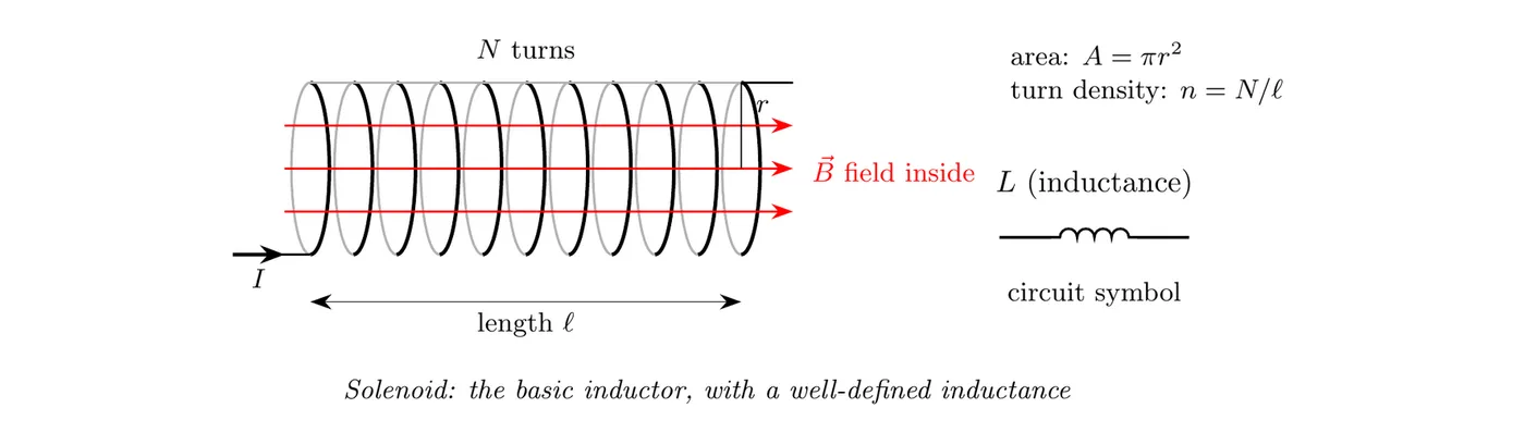
Inductance of a Solenoid
where:
- = inductance (H).
- T·m/A = permeability of free space.
- = total number of turns.
- = cross-sectional area of the solenoid (m²).
- = length of the solenoid (m).
Written with turn density instead:
where is the turn density, or turns per unit length.
What drives it:
- More turns (bigger ) gives more inductance.
- Bigger area (bigger ) gives more inductance.
- Longer solenoid (bigger length ) gives less inductance.
- Tighter spacing (bigger ) gives more inductance.
Why those factors matter:
- More turns build a stronger field for the same current.
- More area means more flux.
- Tighter coils (higher ) make a stronger field.
The Core Material
The formula above assumes an empty (air) core. The AP equation sheet writes the general version, with the core’s permeability in place of :
Here is the magnetic permeability of whatever fills the solenoid (topic 5.1). For air or vacuum, . Slide an iron rod inside and can be hundreds or even thousands of times bigger than , because the iron gets magnetized and adds its own field. The inductance goes up by that same factor. That’s why real inductors and transformers are wound around iron cores.
Self-Inductance
When the current through an inductor changes, the shifting magnetic field induces an EMF right back in the inductor itself. That’s self-inductance.
Self-Induced EMF
where:
- = self-induced EMF (V).
- = inductance (H).
- = rate of change of the current (A/s).
That negative sign is Lenz’s Law again: the induced EMF fights the change in current.
What it means in practice:
- Current rising (): the induced EMF fights the increase, acting like a brake.
- Current falling (): the induced EMF fights the decrease, trying to keep the current going.
An analogy: inductance is electrical “inertia.” It resists changes in current the same way mass resists changes in velocity.
Connection to Faraday’s Law
You can derive self-inductance straight out of Faraday’s Law.
Faraday’s Law:
For a solenoid:
where the field inside is .
So:
Take the time derivative:
And since :
Compare that with and you get:
Which confirms the formula from before.
Another way to define inductance: above is the total flux through all turns. For any coil, that total is proportional to the current, and the constant of proportionality is the inductance:
Here is the flux through one turn. Faraday’s Law then gives the self-induced EMF in one step: .
Energy Stored in an Inductor
An inductor stores energy in the magnetic field its current creates.
The Energy Formula
where:
- = energy stored in the inductor (J).
- = inductance (H).
- = current through the inductor (A).
Where it comes from: to build up the current, the source has to push against the inductor’s EMF. The power going into the inductor is . Add it up as the current grows from 0 to :
The energy is stored in the magnetic field. When the current drops, the field shrinks and the inductor hands that energy back to the circuit.
How it lines up with other energy formulas:
System | Energy Formula | The “inertia” | The “motion” |
Kinetic | Mass | Velocity | |
Capacitor | Capacitance | Voltage | |
Inductor | Inductance | Current |
Where the energy goes:
- The energy in an inductor can get dumped through a resistor as heat.
- It can also get handed over to a capacitor, which produces oscillations.
- Conservation of energy holds throughout.
Example: Inductance and Stored Energy of a Solenoid
Problem: An air-core solenoid has 500 turns, a length of 0.25 m, and a radius of 0.020 m. (a) Find its inductance. (b) Find the energy stored when it carries 2.0 A. (c) The current is cut steadily from 2.0 A to 0 in 0.010 s. Find the size of the induced EMF. (d) Redo (a) to (c) with an iron core that has .
(a) Inductance
(b) Stored energy
(c) Induced EMF
(d) With the iron core
Every answer gets multiplied by 200: H, J, and V.
What it tells you: the iron core gives 200 times the inductance from the same coil of wire. All that stored energy has to go somewhere when the current is cut, which is why switching off a big inductor quickly can make a spark.
Inductors in Circuits
Inductors are key parts of several circuit types.
RL Circuits (Resistor plus Inductor)
- An inductor in series with a resistor.
- The current changes exponentially, with time constant .
- Covered in the next topic.
LC Circuits (Inductor plus Capacitor)
- Energy sloshes back and forth between the inductor and the capacitor.
- Produces AC oscillations.
- Covered in topic 6.6.
Transformers
- Two inductors (coils) that share a magnetic flux.
- They shift AC voltage levels up or down.
- Fundamental to how power distribution works.
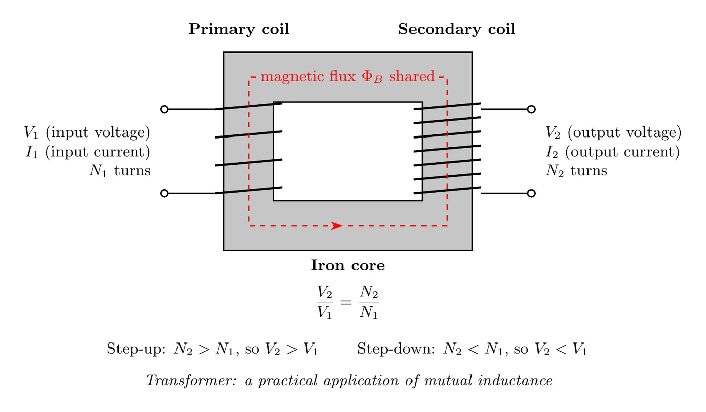
Transformers are everywhere:
- Power distribution (step the voltage up for transmission, back down for homes).
- Phone chargers and laptop power bricks.
- Electric vehicle charging stations.
- Welding equipment.
Example Problem: Self-Induced EMF in an Inductor
Problem:
An inductor with inductance H is wired in series with a resistor and a power supply. The current in the circuit changes with time as:
where A and s.
Find the magnitude of the potential difference (the induced EMF) across the inductor.
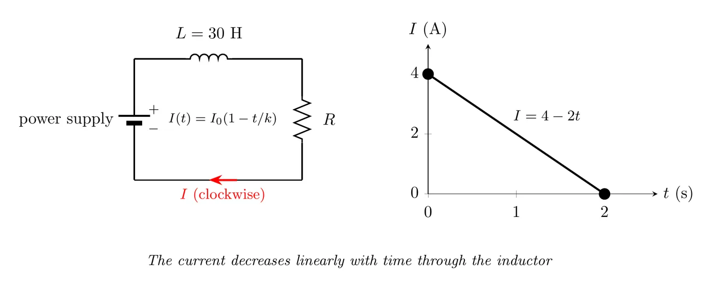
Solution
Step 1: grab the self-inductance formula
We just want the magnitude, so we’re ignoring the negative sign.
Step 2: find how fast the current is changing
We’re given:
Plug in the values:
Expand it:
Step 3: take the derivative
Step 4: compute the magnitude of the induced EMF
Answer: the induced EMF across the inductor has magnitude 60 V.
What it tells you:
- The current is dropping at a steady 2 A/s.
- The inductor fights that drop by generating a 60 V EMF.
- That EMF works to keep the current going, which is Lenz’s Law in action.
- The bigger the inductance, the bigger the opposing EMF.
How Inductors Behave in Circuits
The Instant You Flip the Switch
Current through an inductor can’t change instantly.
- Before the switch closes: .
- Right after the switch closes: , since it can’t jump.
- Long after the switch closes: , the steady state, where the inductor is basically just a wire.
Why? If the current jumped instantly, , which would need an infinite EMF. Not physically possible.
Steady State (DC)
After a long time in a DC circuit:
- The current is constant, so .
- The induced EMF is zero: .
- The inductor acts like a short circuit, essentially a wire with roughly zero resistance.
Summary of Key Formulas
Inductance of a Solenoid
Self-Induced EMF
Energy Stored
Power in an Inductor
Here is the power delivered by the inductor’s EMF. It’s negative while the current is growing, which means the inductor is taking in energy at the rate . It’s positive while the current is falling, when the inductor gives that energy back.
Comparison Table: Capacitor vs. Inductor
Property | Capacitor | Inductor |
Stores | Electric field energy | Magnetic field energy |
Energy | ||
Fights changes in | Voltage | Current |
Relation | ||
DC steady state | Open circuit (no current) | Short circuit (no voltage) |
Symbol | Two short parallel lines (the plates) | A coiled line (the loops of wire) |
Common Mistakes
- Thinking inductors resist current itself. They resist changes in current, not current. In steady DC, an ideal inductor is basically a wire with zero resistance. It’s the rate of change that matters.
- Confusing L (inductance) with ℓ (length). In , the on the left is the inductance and the in the denominator is the solenoid’s length. Some books write both with the same letter , so check which one a problem means.
- Dropping the negative sign in the self-induced EMF. The formula is , not . That sign is Lenz’s Law. You can drop it when you only want a magnitude, though.
- Differentiating the current wrong. When you take , make sure you actually differentiate the given function correctly. In our example, , so , not or .
- Assuming the current can jump instantly. People forget that current through an inductor has to be continuous. The moment a switch opens or closes, the current through the inductor is the same on both sides of that instant, even though the voltage across it can leap dramatically.