

6.5 - Circuits with Resistors and Inductors (LR Circuits)
Introduction to LR Circuits
An LR circuit has a resistor and an inductor wired in series. The resistor burns off energy while the inductor stores it in a magnetic field.
The key behavior: the current changes exponentially over time, and a time constant sets the pace.
Kirchhoff’s Loop Rule for LR Circuits
Apply Kirchhoff’s Loop Rule to an LR circuit with a battery:
where:
- = EMF of the battery (V).
- = current through the circuit (A).
- = resistance (Ω).
- = inductance (H).
- = rate of change of the current (A/s).
What each term is:
- is the voltage drop across the resistor, dissipated as heat.
- is the self-induced EMF in the inductor, fighting the change in current.
This is a differential equation, because that is sitting right in it.
Time Constant for LR Circuits
The time constant tells you how fast the current changes in an LR circuit.
where:
- (tau) = time constant (s).
- = inductance (H).
- = resistance (Ω).
What it means:
- Bigger : the current changes slowly (big inductance or small resistance).
- Smaller : the current changes fast (small inductance or big resistance).
After one time constant ():
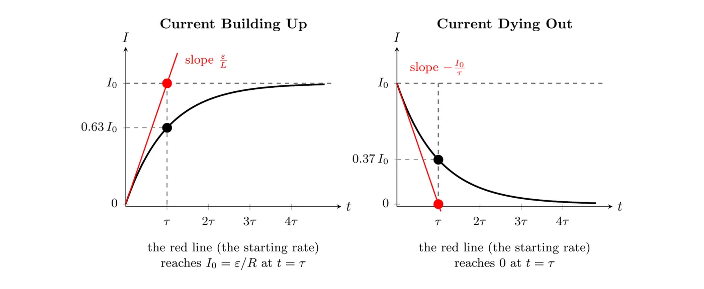
- Charging: the current has climbed to about 63% of its max.
- Discharging: the current has dropped to about 37% of where it started.
After : the circuit is about 99% of the way there, so essentially done.
Another Way to Read τ
Right after the switch closes, the current is zero, so the loop rule gives . The current starts out rising at . If it kept rising at that starting rate, it would reach its final value after:
So the time constant is the time the circuit would take to reach steady state if it kept changing at its starting rate. It doesn’t, because the rate keeps dropping, so it only gets to 63% by then. The same idea works for a current dying out: the starting slope is , and that line hits zero at , when the real current is at 37%.
Circuit Schematic and Behavior
The LR Circuit Setup
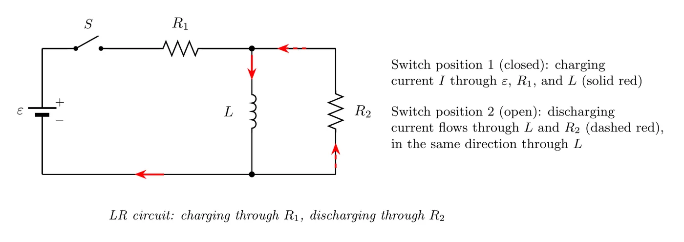
The charging phase: the switch connects the battery, and current builds up in the inductor.
The discharging phase: the switch cuts the battery out, and the inductor dumps its stored energy through resistor .
Charging and Discharging Graphs
Charging: the Current Builds
When the switch closes and hooks up the battery, the current grows exponentially from zero up to its maximum.
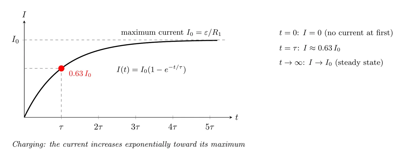
The charging equation:
where is the steady-state current.
Discharging: the Current Decays
When the switch opens and cuts out the battery, the current falls exponentially from its max down to zero.
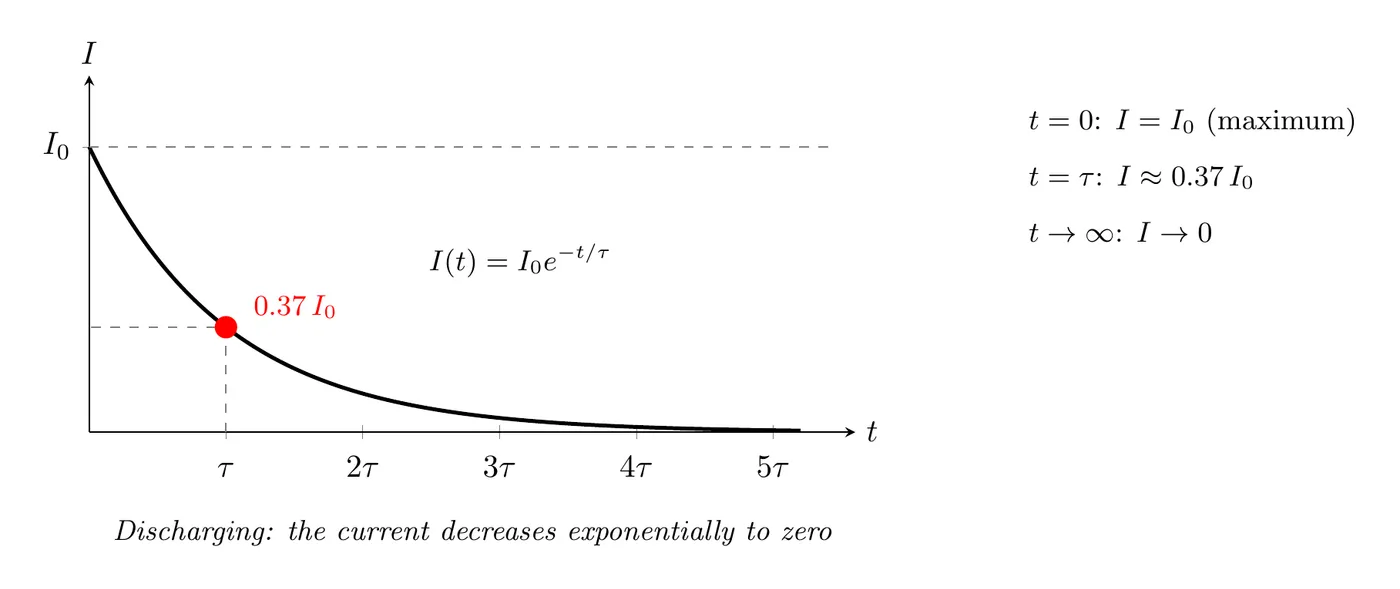
The discharging equation:
where is whatever the current was when the discharge started.
Example Problem: Deriving the Discharge Equation
Problem:
An LR circuit has been hooked up to a battery long enough to reach a steady-state current . Then the switch opens, cutting the battery out and letting the inductor discharge through resistor .
Derive the equation showing that the current is:
where .
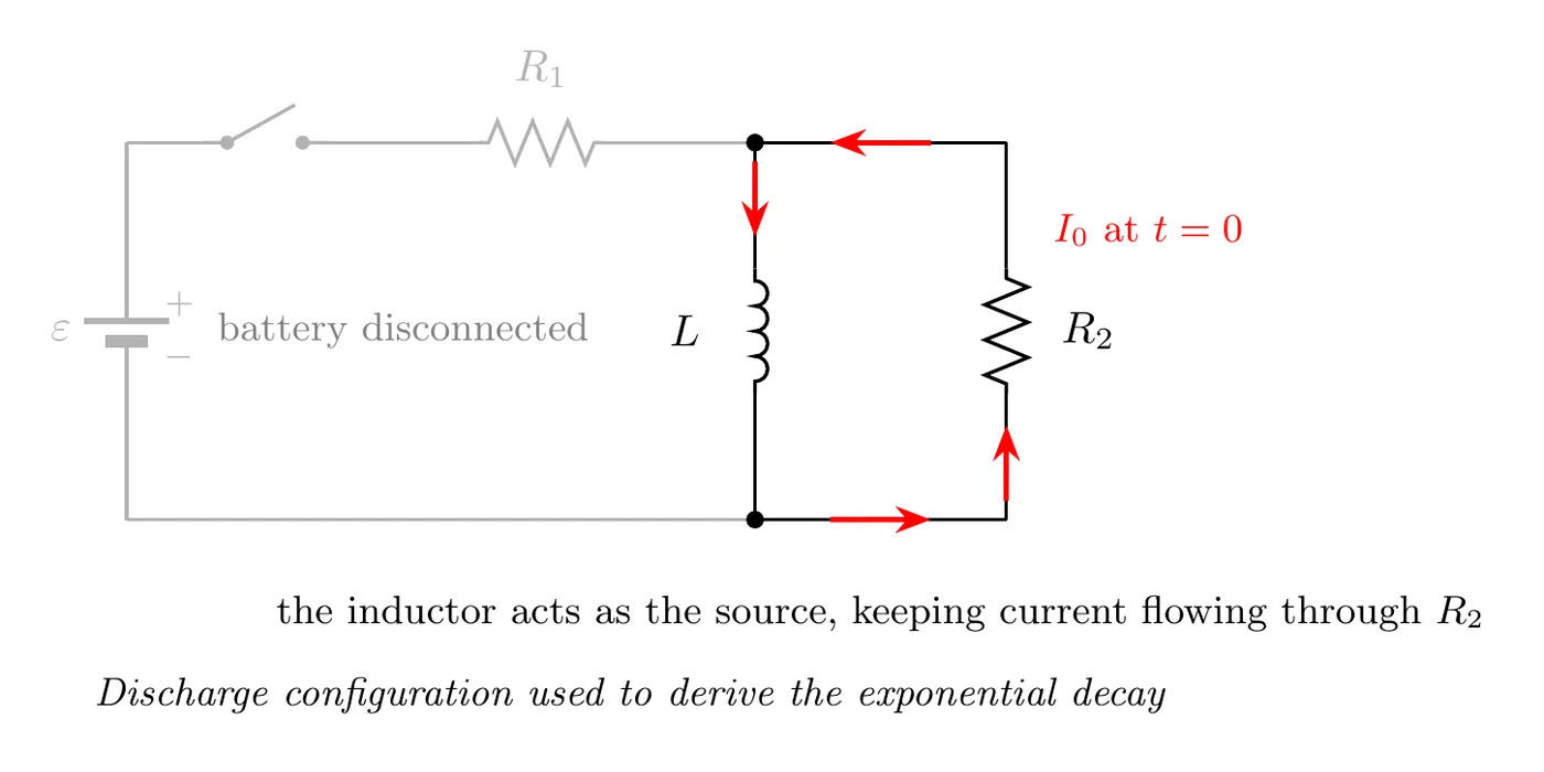
Solution
Step 1: apply Kirchhoff’s Loop Rule with no battery
With the battery gone, the loop equation is:
Where the signs come from (going around the loop in the direction of the current):
- : moving with the current through a resistor, the potential drops by .
- : this is the potential change across the inductor when you move with the current. The minus sign is part of that rule for every inductor. It isn’t there because the current is falling. In fact, since the current is falling, , so this term is positive: the inductor acts like a small battery pushing the current forward, which is how it keeps the current going.
Step 2: rearrange the differential equation
Step 3: separate the variables
Step 4: integrate both sides
The left side:
The right side:
Step 5: put them together
Step 6: exponentiate both sides
Step 7: spot the time constant
Since , we have:
So:
Step 8: the final result
Which confirms the exponential decay of the current during discharge.
Example Problem: Deriving the Charging Equation
Problem: A battery of EMF , a resistor , and an inductor are in series. The switch closes at , when . Solve the loop equation for .
Step 1: write the loop rule
Step 2: separate the variables
Step 3: integrate, starting from zero current
Step 4: solve for the current
Check it: at , . As , , as if the inductor were a plain wire. And the starting slope is , the same as plugging into the loop rule.
Right After a Switch Is Closed or Opened
The current through an inductor can’t jump, so right after a switch moves, the inductor’s current is whatever it was right before. Its EMF does whatever it takes to make that true.
Switch just closed, no current yet: for that instant the inductor carries zero current, like a break in its branch. Its induced EMF is equal in size and opposite in direction to the potential difference applied across its branch, which is exactly what keeps the current at zero. In a single series loop, that means and .
Switch just opened (or the source cut out) while current flows: the inductor keeps the same current going, now through whatever path is left. Its EMF becomes whatever that path needs, . If is large, that can be much bigger than the battery’s EMF, which is why opening a switch on an inductor can make a spark.
After that, everything in the circuit (the current, the inductor’s voltage, the stored energy) changes exponentially until it settles at its new steady state.
Example Problem: Numbers for a Series LR Circuit
Problem: A 9.0 V battery, a 3.0 Ω resistor, and a 0.60 H inductor are in series. The switch closes at . Find (a) the time constant, (b) how fast the current increases right after the switch closes, (c) the current at s, (d) when the current reaches 2.0 A, and (e) the energy stored in the inductor once the current is steady.
(a) Time constant
(b) Starting rate: at , , so the whole 9.0 V is across the inductor:
(c) Current at 0.40 s: the final current is A, so:
(d) Time to reach 2.0 A: set A and solve:
(e) Stored energy at steady state
Steady-State Behavior
After a long time (many time constants), the LR circuit settles into steady state.
Charging Steady State
Long after the switch closes ():
- The current maxes out: .
- The current stops changing: .
- The inductor voltage is , so it acts like a wire.
- All the voltage drops across the resistor: .
Why: once the current stops changing, the inductor has no induced EMF left. It’s just a short circuit at that point.
Discharging Steady State
Long after the switch opens ():
- The current hits zero: .
- Every bit of energy that was in the inductor has been burned as heat in the resistor.
- The circuit is done.
Energy Considerations
The energy the inductor starts with:
During the discharge, all of it gets dissipated as heat in the resistor:
Substitute :
Which is exactly the energy it started with. ✓ Energy is conserved.
Voltage and Energy Over Time
The current isn’t the only thing that changes exponentially. In a series LR circuit, the inductor’s voltage and stored energy follow from , with and for the loop the current is in:
Switch closed (current building up):
- , starting at and decaying to 0.
- , starting at 0 and rising to .
Switch opened (current dying out):
- , starting at and decaying to 0.
- , starting at and decaying to 0.
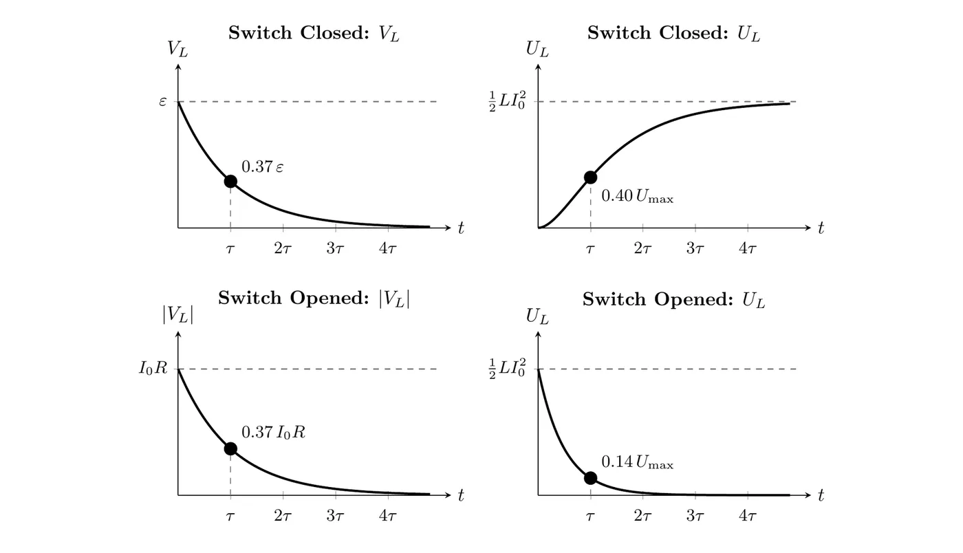
Each graph levels off at a value set by the circuit’s starting conditions. Notice that the energy lags behind the current. At the building current is at 63%, but the energy is only at of its final value. When the current dies out, the energy falls twice as fast as the current (time constant ), so at only of it is left.
Example Problem: An Inductor with Several Resistors
Problem: In the circuit below, the switch has been open for a long time. It closes at .
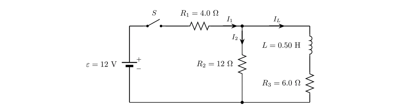
- Find , , and right after the switch closes, and the rate at that moment.
- Find all three currents and the energy stored in the inductor after the switch has been closed a long time.
- Then the switch is opened again. Find the current in each resistor and the size of the inductor’s EMF right after it opens, the time constant of the decay, and the total thermal energy produced afterward.
Solution
(a) Right after closing
The inductor’s current was zero, and it can’t jump, so . For this instant, the inductor’s branch carries no current, and the circuit acts like just and in series:
The potential difference across is V. The inductor’s branch is in parallel with , so it has 9.0 V across it too. With no current, has no voltage across it, so all 9.0 V is across the inductor:
(b) Long after closing
Now the inductor acts like a plain wire, so (12 Ω) is in parallel with (6.0 Ω):
The parallel part has V across it, so A and A. The energy stored in the inductor is:
(While the current builds, the time constant is , where is the resistance the inductor sees with the battery replaced by a wire: in series with and in parallel, , so s.)
(c) Right after opening
The battery and are cut out, so . The inductor still carries 1.0 A, and the only path left is the loop through and . So carries 1.0 A, and carries 1.0 A too, now flowing up (the opposite way from before). The inductor has to push 1.0 A through 18 Ω:
That’s more than the 12 V the battery supplied. The current then dies out with:
All 0.25 J that was stored in the inductor ends up as thermal energy in and .
What it tells you: right after a switch closes, an inductor with no current acts like a break in its branch. A long time later, it acts like a plain wire. Right after a switch opens, it acts like a current source that keeps its current the same for that instant.
Summary of Key Formulas
Time Constant
Charging Current
where
Discharging Current
Voltage Across the Inductor
- Charging: , decaying from down to 0.
- Discharging: , starting at max and decaying to 0.
Comparison: RC vs. LR Circuits
Property | RC Circuit | LR Circuit |
Time constant | ||
Stores | Electric field energy | Magnetic field energy |
What changes | Voltage (on the capacitor) | Current (through the inductor) |
Can’t change instantly | Voltage across C | Current through L |
Charging equation | ||
Discharging equation | ||
Steady state (DC) | Open circuit (no current) | Short circuit (no voltage) |
Same skeleton: both give you exponential behavior with basically identical math.
Common Mistakes
- Using the wrong resistance in the time constant. When the circuit has multiple resistors ( for charging, for discharging), make sure you grab the right one. For discharge, , where is the resistance in the discharge path, not the original charging resistor.
- Dropping the negative sign in the differential equation. When you derive the discharge equation, it’s , negative because the current is falling. Don’t lose that sign.
- Mixing up the charging and discharging equations. Charging looks like , starting at zero and growing. Discharging looks like , starting at max and decaying. That piece belongs to charging only.
- Wrong integration limits. When you solve the discharge differential equation, integrate from to , not from 0, since you start at the maximum current when the discharge kicks off.
- Thinking the current jumps when the switch opens. Current through an inductor has to be continuous. The instant the switch opens, is the same value just before and just after, even though the voltage across the inductor can spike dramatically.