

6.6 - Circuits with Capacitors and Inductors (LC Circuits)
Introduction to LC Circuits
An LC circuit has just a charged capacitor and an inductor, with no resistor and no battery. They’re also called oscillating circuits, because the energy sloshes back and forth between the capacitor and the inductor.
The defining feature: energy keeps moving between:
- Electric field energy in the capacitor.
- Magnetic field energy in the inductor.
An analogy: LC circuits behave exactly like a mass on a spring, with energy trading between kinetic and potential forms.
Conservation of Energy in LC Circuits
You can find the maximum current in an LC circuit with nothing more than conservation of energy.
The Energy Balance
Total energy stays fixed:
Energy in the capacitor:
Energy in the inductor:
At different moments:
Moment | Capacitor | Inductor | Charge | Current |
Maximum charge | ||||
Midpoint | ||||
Maximum current |
The energy conservation equation:
That’s what lets you get the maximum current from the initial charge.
The Simple Harmonic Motion Model
The charge on the capacitor oscillates with simple harmonic motion.
The Differential Equation
Apply Kirchhoff’s Loop Rule to an LC circuit:
Since :
Substituting:
Rearranging:
That’s exactly the shape of the simple harmonic oscillator equation:
The thing to notice: the second derivative of is proportional to . The only functions that pull that off are the trig functions, sine and cosine.
Angular Frequency and Period
Angular Frequency
Match the differential equation up with the SHM form:
Check it by plugging in: try . Its second derivative is . That matches only if , so the circuit can only oscillate at . This is the on the equation sheet.
where:
- = angular frequency (rad/s).
- = inductance (H).
- = capacitance (F).
What it means: how fast the charge and current oscillate.
Period of Oscillation
The period is how long one full cycle takes:
Substituting :
where:
- = period of oscillation (s).
- = inductance (H).
- = capacitance (F).
What it means: the time for the charge to go through one full cycle, from to and back to . The energy moves from the capacitor to the inductor and back twice in that time, since the capacitor stores the same energy whether its charge is or .
The Oscillation Cycle
The energy trades back and forth between electric and magnetic forms:
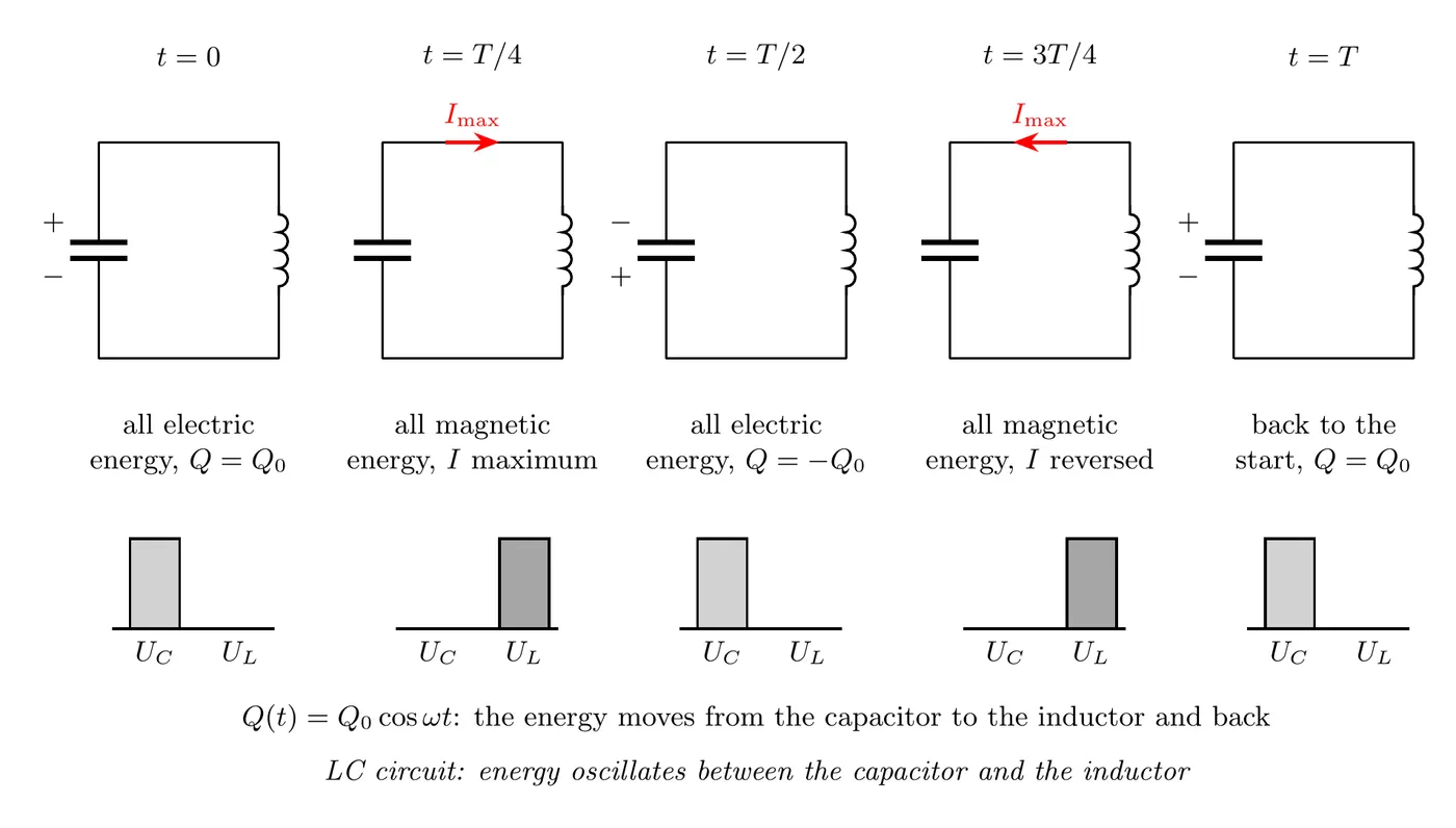
The key points:
- When is at its max, , since all the energy is in the capacitor.
- When is at its max, , since all the energy is in the inductor.
- The total energy never changes.
- In an ideal circuit with no resistance, this goes on forever.
The Analogy: Mass on a Spring
LC circuits are mathematically identical to a mass bouncing on a spring.
Mass-Spring System | LC Circuit |
Mass | Inductance |
Spring constant | |
Position | Charge |
Velocity | Current |
Kinetic energy | Magnetic energy |
Potential energy | Electric energy |
Same math, different physics. Everything you know about simple harmonic motion carries straight over to LC circuits.
Time Dependence Functions
The charge and current both wobble sinusoidally with time.
Charge on the Capacitor
or
where is the maximum charge, the amount it starts with at .
Current Through the Circuit
Since :
And the maximum current:
Starting with Current Instead of Charge
fits a circuit that starts with a fully charged capacitor and no current. In general , and the starting conditions set and . A common case: the capacitor starts uncharged and the inductor starts with current . Then:
The charge on the capacitor peaks at , a quarter period after the start.
Example Problem: Maximum Current from Energy Conservation
Problem:
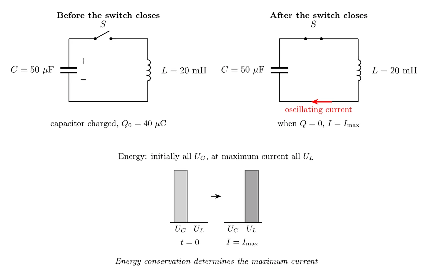
A capacitor with capacitance μF gets fully charged to μC. It’s then wired in series with an inductor of inductance mH through an open switch. After the switch closes, what’s the maximum current through the inductor?
Solution
Step 1: apply conservation of energy
When the capacitor is fully charged, all the energy is in it:
When the current peaks, all the energy is in the inductor:
Energy conservation says those are equal:
Step 2: solve for the maximum current
Cancel the on both sides:
Step 3: plug in the numbers
Convert everything to SI first:
- μC C
- μF F
- mH H
Answer: the maximum current through the inductor is 40 mA, or 0.04 A.
Example Problem: An Inductor Charging a Capacitor
Problem: In the circuit below, the switch has been at for a long time, so a steady current flows through the battery, the resistor, and the inductor. The capacitor is uncharged. At , the switch moves to . That cuts out the battery and resistor and connects the inductor to the capacitor.
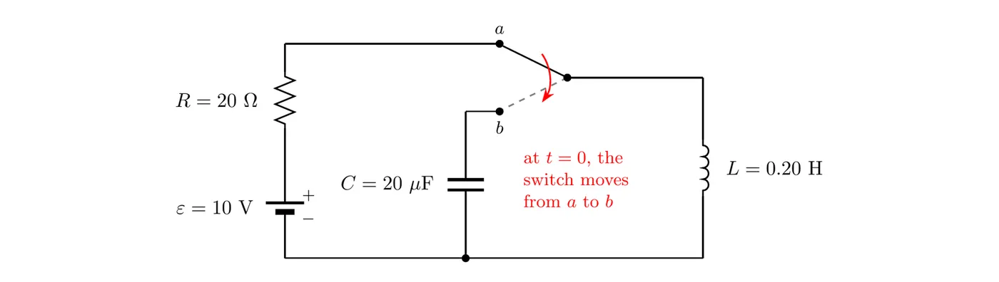
- Find the current in the inductor just before the switch moves, and the energy it stores.
- Find the maximum charge on the capacitor and the maximum voltage across it.
- Find the angular frequency, the period, and the first time the capacitor is fully charged.
- Find the charge and the current at ms, and check that energy is conserved.
Solution
(a) Before the switch moves
After a long time, the inductor acts like a wire, so:
(b) Maximum charge and voltage
The inductor’s current can’t jump, so right after the switch moves, the 0.50 A flows onto the capacitor. When the capacitor is fully charged, and all the energy is in the capacitor:
The capacitor ends up at 50 V even though the battery was only 10 V. That energy came from the inductor’s magnetic field.
(c) Frequency and timing
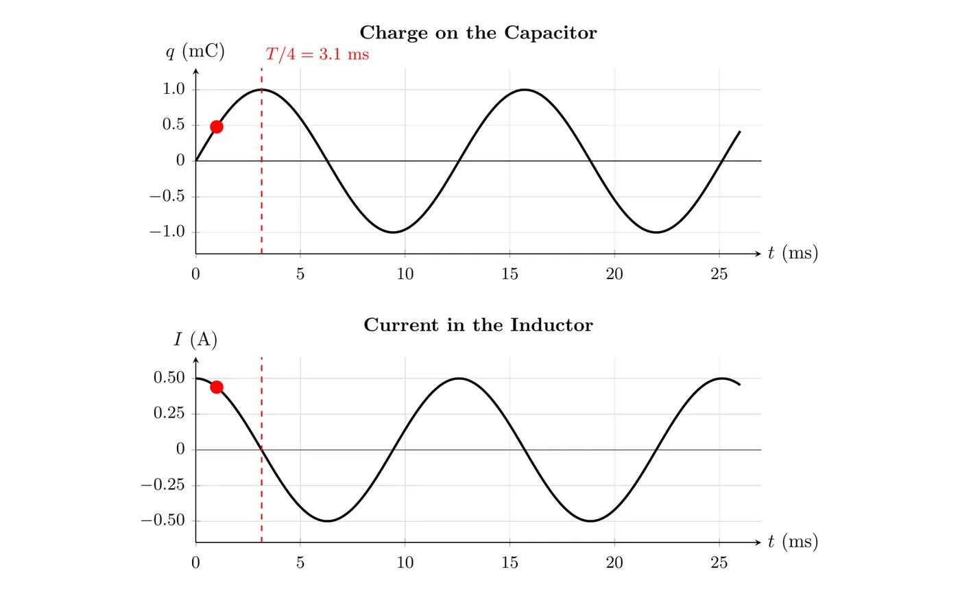
The capacitor starts uncharged, so it’s first fully charged a quarter period later: s (3.1 ms).
(d) At 1.0 ms
Use and with rad:
The total is still 0.025 J, the same as at the start. ✓
The graphs show both functions with real scales. The red dots mark ms, and the dashed line marks , where the charge peaks and the current is zero.
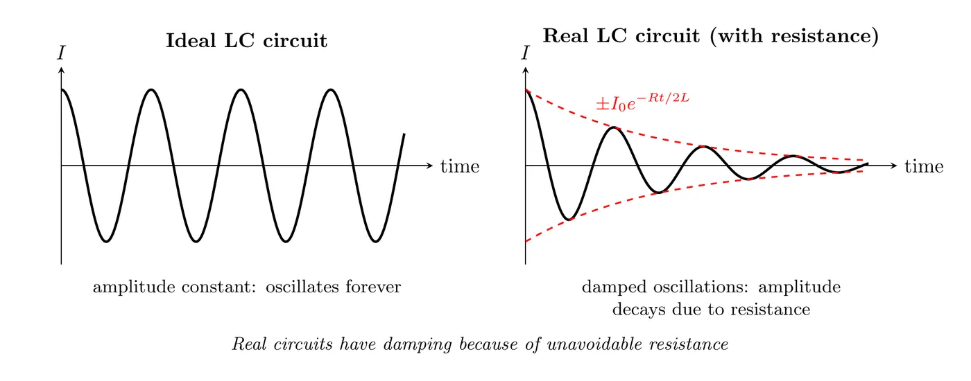
Ideal vs. Real LC Circuits
The Ideal LC Circuit
What we assume:
- No resistance ().
- No energy loss.
- The oscillations run forever at a constant amplitude.
The result: energy bounces between the capacitor and inductor indefinitely.
The Real LC Circuit
What actually happens:
- There’s always some resistance in the wires and the inductor coil.
- Energy slowly leaks away as heat.
- The oscillations get damped, so the amplitude shrinks over time.
- Eventually all the energy is gone.
Summary of Key Formulas
Angular Frequency
Period
Maximum Current from Energy
Energy Conservation
Charge and Current Functions
Comparison: Three Circuit Types
Circuit | Components | Time Constant or Period | Energy Behavior |
RC | Resistor + Capacitor | Exponential climb (charging) or decay to zero (discharging) | |
LR | Inductor + Resistor | Exponential climb to steady state, or decay to zero when the source is removed | |
LC | Inductor + Capacitor | Oscillates forever (in the ideal case) |
Applications of LC Circuits
1. Radio Tuning Circuits
- Twist the variable capacitor to change and shift the resonant frequency.
- That’s how you pick a radio station.
2. Oscillators
- They generate AC signals at specific frequencies.
- Used in signal generators and transmitters.
- Also in the clock circuits inside electronics.
3. Filters
- LC circuits block or pass specific frequencies.
- Used in audio gear and communication systems.
- Resonance happens at .
4. Tank Circuits
- They park energy temporarily.
- Shuttle it between the capacitor and the inductor.
- Used in switching power supplies.
Common Mistakes
- Forgetting to convert units. LC circuits love microfarads (μF), millihenrys (mH), and microcoulombs (μC). Always get everything into SI (F, H, C) before you calculate. Skipping this is the number one source of numerical errors.
- Using the period formula as if it were a time constant. LC circuits have a period, , for their oscillations, not a time constant . Don’t confuse it with RC circuits () or LR circuits (), where you get exponential decay instead.
- Thinking energy leaks away in an ideal LC circuit. In an ideal LC circuit with no resistance, the total energy is conserved and oscillates forever. It doesn’t decay, it just changes form. Only real circuits with resistance actually lose energy.
- Using the wrong capacitor energy formula in terms of Q. It’s , NOT . The goes in the numerator. That’s different from , where the sits next to the up top.
- Forgetting that current and charge are 90° out of phase. When the charge is at its max, the current is zero. When the current is at its max, the charge is zero. They never peak together. It’s just like position and velocity in SHM, a quarter cycle apart.
BackNext