

2.2 - Forces and Free-Body Diagrams
What Is a Force?
A force is a vector that describes an interaction between objects or systems. You can think of forces as pushes or pulls.
Every force has a source. A force on an object always comes from an interaction with some other object or system. For every force on your free body diagram, you should be able to name what’s exerting it: Earth (gravity), the floor (normal force), the rope (tension), and so on. If you can’t name the source, the force isn’t real.
Nothing can push itself. An object or system can’t exert a net force on itself. Sit in a stalled car and push on the dashboard: your hands push the dashboard forward, but your back pushes the seat backward just as hard. Both forces are inside the you-and-car system, so they cancel and the car doesn’t roll. To move it, you have to get out and push on it from outside, with your feet pushing on the ground.
Forces come in two main types.
1. Contact Forces
Contact forces happen when objects physically touch. The interaction needs direct physical contact between the object and the system.
Examples:
- Normal force (a surface pushing on an object).
- Friction force (surfaces sliding or trying to slide).
- Tension force (a rope or string pulling).
- Applied force (a person pushing).
Where contact forces come from: zoom in far enough and nothing actually touches. Contact forces are the large-scale result of electric forces between the atoms of the two surfaces. When a book sits on a table, the atoms at the surfaces get pushed slightly closer together and their electrons repel, so the table’s surface squishes a tiny bit, like a very stiff spring, and pushes back. That push is the normal force. Friction comes from the same electric forces acting where the tiny bumps of the two surfaces meet.
2. Field Forces
Field forces happen when an object feels a force while inside a field, without any direct contact.
Examples:
- Gravitational force (objects in a gravitational field).
- Electric force (charged objects in an electric field).
- Magnetic force (magnetic objects in a magnetic field).
In mechanics, you mostly deal with gravitational fields.
Problem Solving Strategy: Draw, Sum, Solve
The systematic way to tackle force problems has three steps:
1. Draw a free body diagram showing all the forces.
2. Sum the forces in each direction using Newton’s Second Law.
3. Solve for the unknowns.
Free Body Diagrams (FBD)
A free body diagram is a picture showing all the forces acting on a single object or system.
Rules for Drawing Free Body Diagrams
- Represent the object as a dot or a simple box (usually a dot on the AP exam).
- Draw the force vectors as arrows starting from the center of mass.
- Only include forces acting on the object from the environment, not forces the object exerts on other things.
- Keep the force magnitudes relatively accurate, so larger forces get longer arrows.
- Label each force clearly with the right notation (like , , ).
- Draw forces, not components. On the AP Physics C exams, each force is one straight arrow starting on the dot and pointing in the force’s direction. Don’t add component arrows to the free body diagram. Break forces into components separately, in your equations.
- Draw same-direction forces side by side. If two forces point the same way, draw them as two separate arrows next to each other, both starting at the dot, never stacked on top of each other.
Example: Two Forces in the Same Direction
Problem: a 2.0 kg textbook rests on a table while you press straight down on it with a 15 N push. Draw the free body diagram and find the normal force from the table. Use m/s².
DRAW: three forces act on the book: its weight N down, your push N down, and the normal force up. Weight and your push both point down, so they’re drawn side by side.
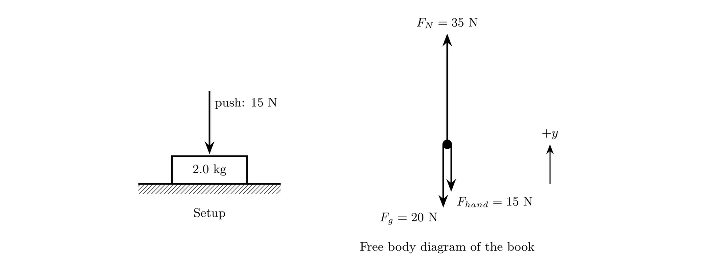
SUM: the book isn’t accelerating, so with up as positive,
SOLVE:
Answer: the table pushes up with 35 N, more than the book’s 20 N weight. The normal force is whatever it takes to keep the book from sinking into the table.
Choosing a Coordinate System
Here’s an important principle: choose your coordinate axes so that one axis is parallel to the direction of acceleration (or potential acceleration) of the object.
Standard Horizontal/Vertical System
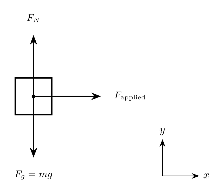
For objects on horizontal surfaces, use the standard orientation with x horizontal and y vertical.
Tilted Coordinate System for Inclines
For incline plane problems, tilt your coordinate system so that:
- The x-axis is parallel to the incline (the direction of motion or acceleration).
- The y-axis is perpendicular to the incline.
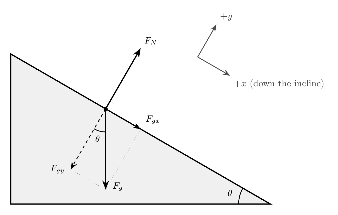
Why tilt the coordinate system?
- It puts as many unknown forces as possible into a single dimension.
- The weight (which you know: ) gets broken into components.
- Unknown forces like the normal force and friction stay along a single axis.
Common Forces in Free Body Diagrams
Gravitational Force (Weight)
or simply for the magnitude.
- Direction: always straight down, toward the center of Earth.
- Magnitude: , where is the mass and m/s² (AP Physics C rounds it to 10 m/s² for calculations, see Topic 1.3).
Normal Force
- Direction: always perpendicular to the contact surface, pointing away from it.
- Magnitude: varies with the other forces, and you often find it using .
Important: the normal force does not always equal the weight. It only equals for objects at rest on horizontal surfaces with no other vertical forces.
Tension Force
- Direction: along the rope, string, or cable, pulling away from the object.
- Magnitude: varies with the situation.
Friction Force
- Direction: opposes the motion or potential motion, parallel to the contact surface.
- Magnitude: depends on whether static or kinetic friction applies.
Applied Force
- Direction: specified in the problem.
- Magnitude: given in the problem.
Air Resistance / Drag Force
Often velocity-dependent: or .
- Direction: opposes the velocity, so opposite to the motion.
- Magnitude: depends on the velocity.
Example Problem: Snowboarder on an Incline with Air Resistance
Problem: A snowboarder of mass heads down a frictionless slope that makes an angle with the horizontal. The snowboarder starts from rest at and feels a velocity-dependent air resistance force (magnitude ), where is the snowboarder’s speed and is a positive constant.
- Draw a free body diagram for the snowboarder going down the slope, and label all the forces.
- Write an equation using Newton’s Second Law in the direction parallel to the incline. Give it as a differential equation in terms of , , , , and .
- What is the terminal (maximum) velocity of the snowboarder?
Part (a): Free Body Diagram
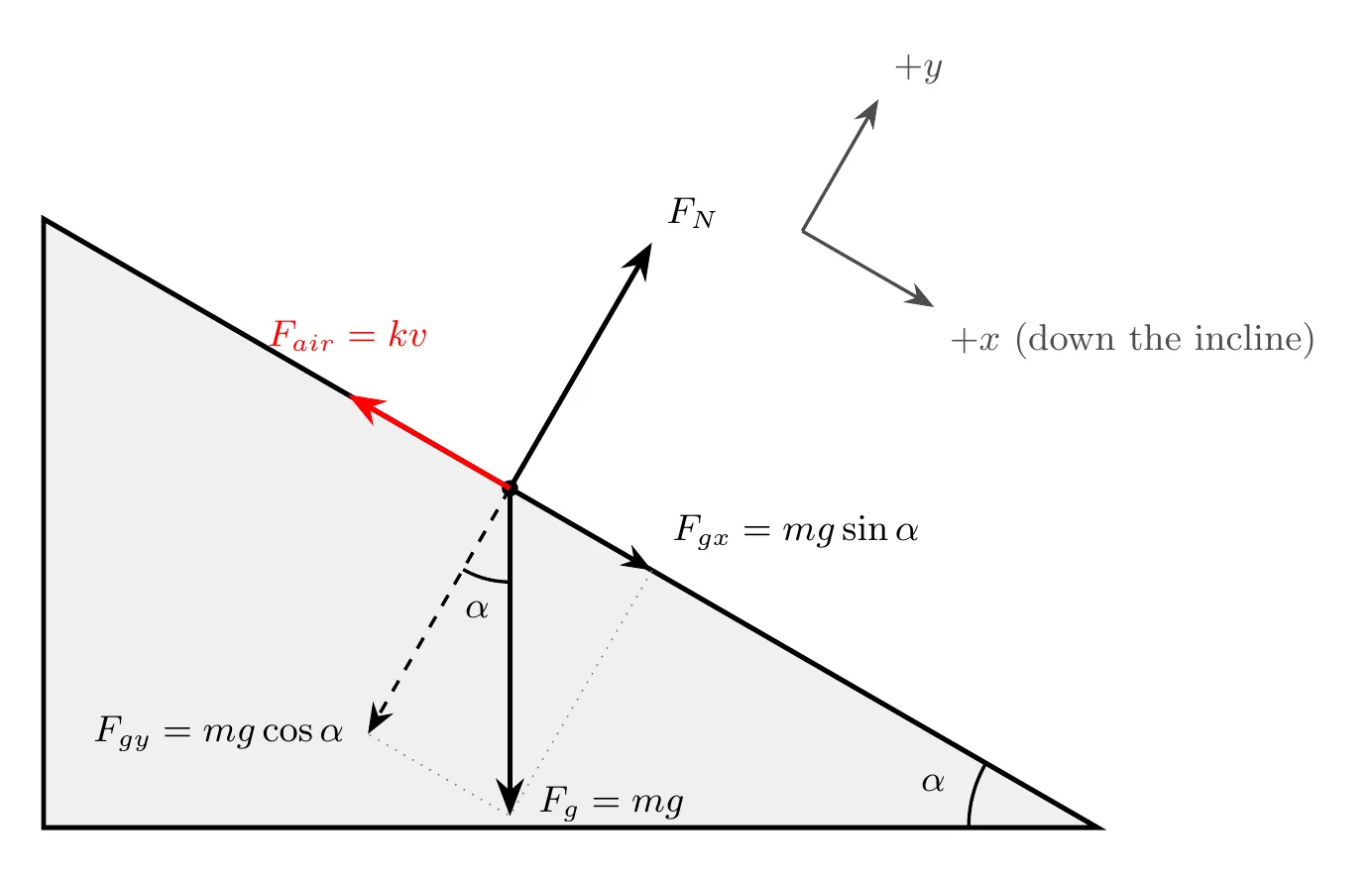
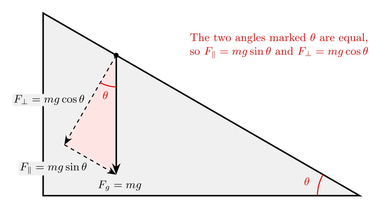
The forces acting on the snowboarder:
- Weight (gravitational force): pointing straight down.
- Component parallel to the incline: (down the slope, +x direction).
- Component perpendicular to the incline: (into the slope, -y direction).
- Normal force: perpendicular to the incline surface (away from the surface, +y direction).
- Air resistance: pointing up the incline (opposing the motion, -x direction).
What the exam wants for part (a): just the three forces, , , and , each drawn as one arrow from the dot. The components drawn in the figure ( and ) are only there to set up part (b). On your own diagram, leave them off and handle the components in your equations.
Part (b): Newton’s Second Law as a Differential Equation
Apply Newton’s Second Law in the x-direction (parallel to the incline):
The forces in the x-direction:
- Positive x-direction: .
- Negative x-direction: .
Since acceleration is the derivative of velocity with respect to time:
The differential equation:
You can also write it as:
Part (c): Terminal Velocity
Terminal velocity is when the acceleration hits zero, meaning the net force is zero. At that point, the snowboarder moves at constant velocity.
Set
(equivalently, ):
Solve for :
The read: as the snowboarder speeds up, the air resistance grows until it exactly balances the component of weight pulling them down the slope. At that point, the net force is zero and they keep a constant velocity.
Key Relationships for Incline Problems
For an object on an incline at angle to the horizontal:
Weight components:
- Parallel to the incline: .
- Perpendicular to the incline: .
Important: the angle between the incline and the horizontal is the same as the angle between the weight vector and the perpendicular component of the weight.
Common Mistakes
- Including forces the object exerts on others. A free body diagram should only show forces acting on the object, not forces the object exerts on other things. Don’t include the force the snowboarder exerts on the slope, for instance.
- Drawing forces from the wrong point. All the force vectors should start from the center of mass (the dot), not from the edges or surfaces.
- Using the wrong coordinate system on inclines. Always tilt your axes to match the incline. Trying to use horizontal and vertical axes for incline problems makes the math much harder.
- Assuming the normal force equals the weight. That’s only true for objects on horizontal surfaces with no other vertical forces. On an incline, , not .
- Using the wrong angle in the weight components. On an incline at angle , the parallel component is (not cosine) and the perpendicular component is (not sine).
- Forgetting that velocity-dependent forces change direction. Forces like air resistance () always oppose the motion, so their direction flips if the object changes direction.
- Making all the force arrows the same length. Force magnitudes should be relatively accurate. If one force is clearly bigger, draw it with a longer arrow.
- Not labeling forces clearly. Every force needs a clear label with the right subscript: , , , and so on.
- Confusing mass and weight. Mass () is in kg. Weight () is a force in newtons (N).
- Setting up differential equations wrong. Remember that . When you have velocity-dependent forces, your equation naturally becomes a differential equation.